Sintering mould

A mold and mold height technology, applied in the direction of manufacturing tools, ceramic molding machines, etc., can solve the problems of increasing equipment costs and use costs, poor pressure resistance of graphite molds, easy cracking of graphite molds, etc. The effect of increased service life

Inactive Publication Date: 2012-08-15
SOUTH CHINA NORMAL UNIVERSITY
View PDF5 Cites 6 Cited by
  • Summary
  • Abstract
  • Description
  • Claims
  • Application Information

AI Technical Summary

Problems solved by technology

The use of such graphite molds has the following problems: (1) It is necessary to add some additional vacuum chambers to prevent them from being oxidized at high temperatures, which increases equipment costs and use costs; (2) The pressure resistance of graphite molds is relatively poor, and imported molds The maximum withstand pressure of graphite is usually lower than 80MPa. When the sample is withdrawn from the mold after sintering, the graphite mold is easy to crack; (3) the current graphite molds are all cylindrical
Although the coefficient of thermal expansion of graphite is at least 10 smaller than that of metal 6 order of magnitude, but some samples themselves shrink when heated and expand when cooled, and are tightly squeezed into the mold after cooling down from high temperature. If they are forced out, the samples are often crushed

Method used


Image

  • Sintering mould
  • Sintering mould
  • Sintering mould

Examples


Embodiment

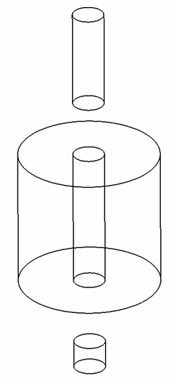
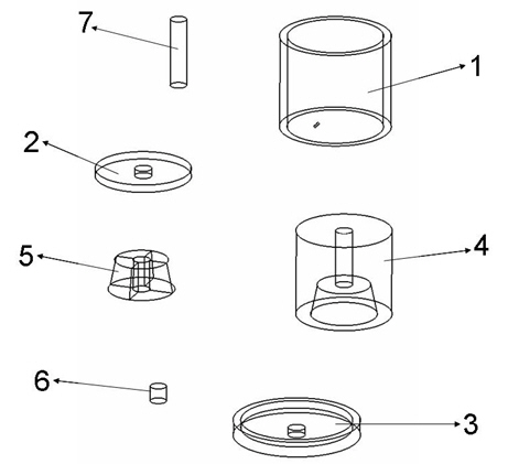
[0020] The structure diagram of the present invention is as figure 2 As shown, the sintering mold of the present invention includes an outer sleeve 1, a bottom cover 2, a top cover 3, an upper mold 4, a lower mold 5, a lower graphite rod 6, and an upper graphite rod 7, wherein the bottom cover 2 and the top cover 3 Installed on the bottom and top of the outer sleeve 1 respectively, the lower mold 5 is placed in the hollow cavity provided by the outer sleeve 1 and placed on the bottom cover 2, the lower part of the upper mold 4 is set on the outside of the lower mold 5, and the lower mold The rod 6 is inserted in the cavity provided by the lower die 5 , and the upper graphite rod 7 is inserted in the cavity provided on the top of the upper die 4 and placed on the top of the lower graphite rod 6 .

[0021] Above-mentioned lower die 5 is a conical circular frustum with a small upper part and a larger lower part.

[0022] Above-mentioned lower mold 5 is assembled into conical ci...

example 1

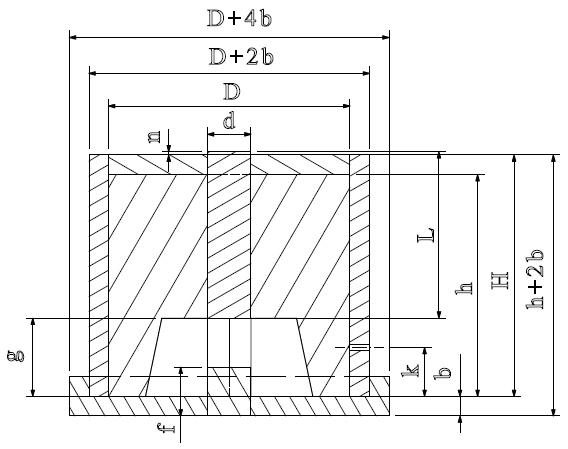
[0033] Example 1: The material of the outer sleeve 1 is corundum. If the sample diameter d is 5mm and the height is 2mm, figure 2 The diameter of middle and lower graphite rod 6 and upper graphite rod 7, the inner diameter of bottom cover 2, top cover 3 upper die 4, lower die 5 all get 5mm. The outer diameter D of the upper mold 4 is 50 mm. The outer diameter of the bottom of the lower mold 5 is 12.5mm. The thickness b of the outer sleeve 1, the bottom cover 2 and the top cover 3 is 4mm. The inner diameter of the outer sleeve 1 and the outer diameter of the top cover 3 are 50mm. The inner diameter of the wall of the bottom cover 2 is 58 mm and the outer diameter is 66 mm. The length f of the lower graphite rod 6 is 5mm. The height g of the lower mold 5 is 3 mm, and the angle between the side of the lower mold 5 and the vertical direction is 5 mm. o . The graphite mold height h is 30mm. The length L of the upper graphite rod 7 is 35 mm, and the length n of the graphite...

example 2

[0034] Example 2: The material of the outer sleeve 1 is zirconia. If the sample diameter d is 100mm and the height is 4mm, figure 2The diameter of middle and lower graphite rod 6 and upper graphite rod 7, the inner diameter of bottom cover 2, top cover 3 upper die 4, lower die 5 all get 100mm. The outer diameter D of the upper mold 4 is 200mm. The outer diameter of the bottom of the lower mold 5 is 100mm. The thickness b of the outer sleeve 1, the bottom cover 2 and the top cover 3 is 2 mm. The inner diameter of the outer sleeve 1 and the outer diameter of the top cover 3 are 200mm. The inner diameter of the wall of the bottom cover 2 is 204mm, and the outer diameter is 208mm. The length f of the lower graphite rod 6 is 8 mm. The height g of the lower die 5 is 10 mm, and the angle between the side of the lower die 5 and the vertical direction is 15 mm. o . The graphite mold height h is 40mm. The length L of the upper graphite rod 7 is 40 mm, and the length n of the gr...


PUM

PropertyMeasurementUnit
melting pointaaaaaaaaaa
pore sizeaaaaaaaaaa
heightaaaaaaaaaa

Abstract

The invention provides a sintering mould. The sintering mould comprises an outer sleeve, a bottom cover, a top cover, an upper mould, a lower mould, a lower graphite rod and an upper graphite rod, wherein the bottom cover and the top cover are respectively arranged at the bottom and the top of the outer sleeve; the lower mould is placed in a hollow cavity arranged on the outer sleeve and is placed on the bottom cover; the lower part of the upper mould is sleeved at the outer side of the lower mould and the lower graphite rod is inserted into a hollow cavity arranged in the lower mould; and the upper graphite rod is inserted into a hollow cavity arranged in the upper mould and is placed at the top of the lower graphite rod. The three components including the outer sleeve, the bottom cover and the top cover are in a separated design so that the loading of a sample and the replacing of a graphite mould are very easy. A cylindrical protection sleeve of the outer sleeve has the function of preventing from oxidizing the graphite mould at a high temperature, and also increases the compression strength of the graphite mould so as to improve the compression capability is improved by at least 1.5 times. The sample can be more easily taken out through a tapered round table design of the lower mould. When the sintering mould is used at the high temperature, a vacuum cavity does not need to be additionally arranged, a mould unloading process does not need to be forcedly processed, and the sample integrity is 100%, so that the service life of graphite is prolonged.

Description

technical field [0001] The invention relates to a sintering mould, which belongs to the modification technology of the sintering mould. Background technique [0002] In the field of special ceramics and thermoelectric bulk materials, ultra-high temperature and rapid sintering of nanostructure samples is often required. The molds of these high-temperature sintered samples often use graphite molds with high melting point and small expansion coefficient (the melting point of graphite is above 3500°C). Its typical structure is as figure 1 As shown, the main body is cylindrical, and the powder sample is placed in the inner circular cavity. When pressing the sample, graphite rods are placed at both ends of the powder sample to apply pressure. sample. The use of such graphite molds has the following problems: (1) It is necessary to add some additional vacuum chambers to prevent them from being oxidized at high temperatures, which increases equipment costs and use costs; (2) The ...

Claims


Application Information

Patent Timeline
Patent Type & Authority Applications(China)
IPC IPC(8): B22F3/12B28B7/42
Inventor 何琴玉陈振瑞李炜罗海津雷正大张勇王银珍余颖刘俊明李萍冯寿廷
Owner SOUTH CHINA NORMAL UNIVERSITY
Why Eureka
Try Eureka