Sequential deslagging control device for soaking tanks and automatic deslagging soaking tank

The technology of a control device and a timing controller is applied in the field of strip steel processing equipment, which can solve the problems of no slag discharge device, reduced soaking effect, pollution of chemical solvents, etc., so as to avoid scratches and embossing, and improve product quality. level, the effect of reducing the impact of cleanliness

Active Publication Date: 2012-08-15
攀钢集团西昌钢钒有限公司
View PDF7 Cites 4 Cited by
  • Summary
  • Abstract
  • Description
  • Claims
  • Application Information

AI Technical Summary

Problems solved by technology

[0003] During the immersion treatment of the strip steel, through the chemical and physical reactions between the chemical solvent and the residue on the surface of the strip steel, a large number of saponified salts, hydrophilic groups, iron filings and other impurities will be formed. These impurities are denser than the chemical solvents. With the long-term operation of the soaking tank, these impurities will accumulate at the bottom of the sinking roller of the soaking tank, forming a thick slurry layer. When the strip passes through the slurry layer through the sinking roll, the slurry layer will be destroyed. Squeezed between the strip steel and the surface of the sinking roll, the hard substances in the slurry will damage the surface quality of the strip steel and the sinking roll; at the same time, the slurry layer will also pollute the chemical solvent and reduce the cleanliness of the chemical solvent
The problem of the prior art is that there is no slurry discharge device at th

Method used


Image

  • Sequential deslagging control device for soaking tanks and automatic deslagging soaking tank
  • Sequential deslagging control device for soaking tanks and automatic deslagging soaking tank

Examples


Example Embodiment

[0017] Hereinafter, exemplary embodiments of the present invention will be described in further detail with reference to the accompanying drawings.

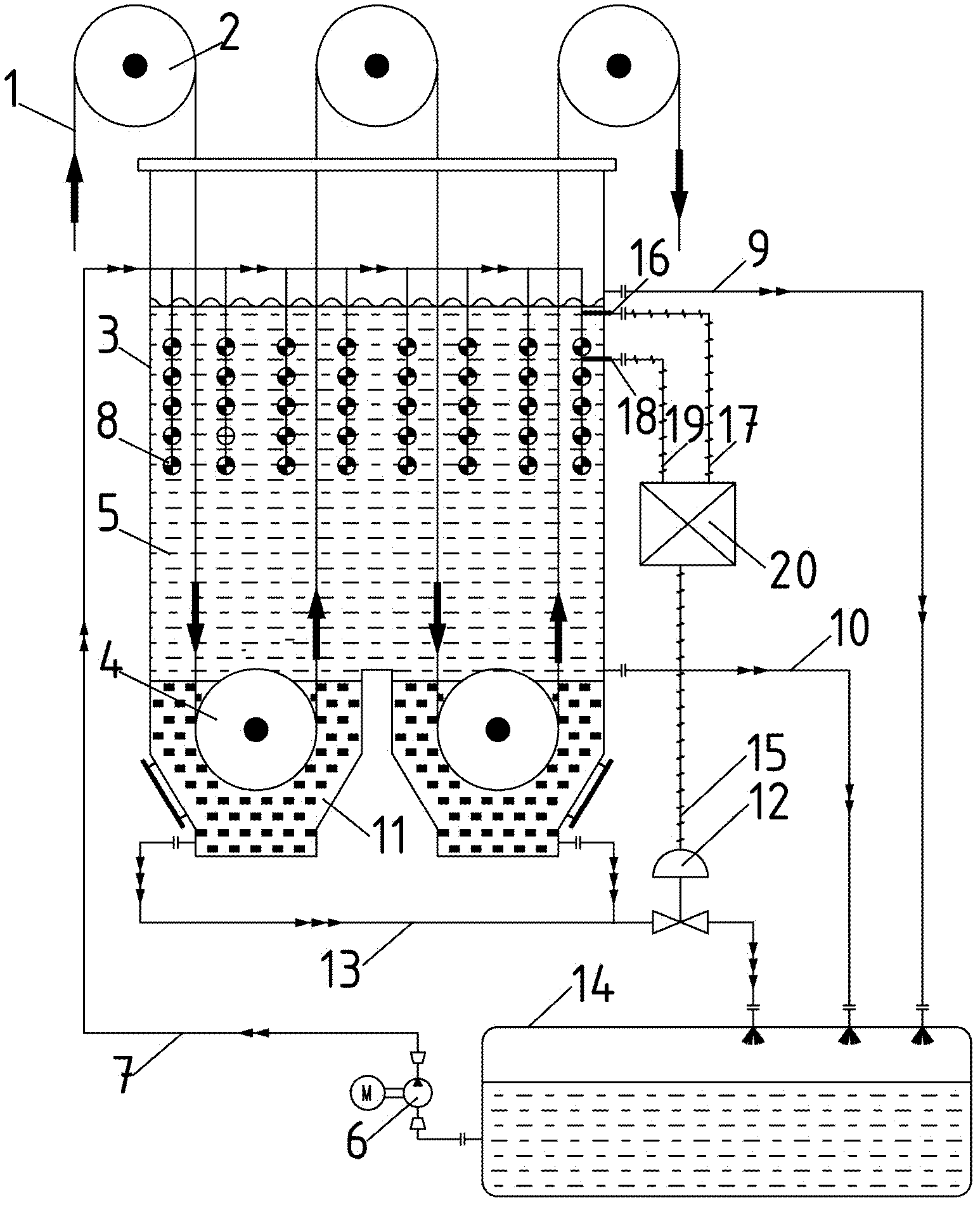
[0018] figure 1 It is a structural schematic diagram of the timing sequence slag discharge control device of the soaking tank and the automatic slag discharge soaking tank of the exemplary embodiment of the present invention. like figure 1 As shown, the sequential slag discharge control device of the soaking tank in this embodiment includes a slag discharge pipe 13, an automatic slag discharge valve 12 and a control unit. Wherein, a slag discharge pipe 13 is arranged at the bottom of the soaking tank 3 to discharge the slurry 11 , and an automatic slag discharge valve 12 is arranged on the slag discharge pipe 13 to control the discharge of the slurry 11 . The control unit is used to control the opening and closing of the slag discharge automatic valve 12. Specifically, the control unit includes a sequence controller 20, a first...


PUM


Abstract

The invention discloses a sequential deslagging control device for soaking tanks and an automatic deslagging soaking tank. The sequential deslagging control device for soaking tanks can quickly carry out sequential discharge on slurry deposited in a soaking tank at a cleaning section of a continuous annealing and galvanization unit according to the actual production, and through the sequential opening and closing of an automatic deslagging valve, a situation that slurry is accumulated at the bottom of a sinking roller of the soaking tank is effectively prevented, thereby avoiding the influences of the slurry on the surface qualities of strip steel and the sinking roller; through a liquid level difference between two liquid level switches, the replacement ratio of new and old chemical solvents in the soaking tank is accelerated, and the quantity of a fresh chemical solvent in the soaking tank is ensured as large as possible, thereby facilitating a situation that the chemical solvent carries out better chemical and physical reactions with the strip steel, and improving the surface cleaning effect of the strip steel; and the timely discharge of the slurry ensures the cleanliness of the chemical solvents in the soaking tank, and the slurry does not reversely pollute the chemical solvents in the soaking tank, thereby enhancing the cleanliness of the chemical solvents, and improving the cleaning effect of the chemical solvents.

Description

technical field [0001] The invention relates to strip steel processing equipment, more specifically, to a sequential slag discharge control device for a immersion tank used in the cleaning section of a continuous annealing and galvanizing unit and a immersion tank with an automatic slag discharge function. Background technique [0002] In the continuous annealing and galvanizing unit, the cleaning section cleans the strip. The cleaning section includes hot alkali soaking tank, scrubbing tank, electrolytic soaking tank, rinsing tank, etc. The tank body with soaking function mainly refers to hot alkali soaking tank and electrolytic soaking tank. The main function of the soaking tank is to use chemical solvents (including NaOH and active agents, etc.) to chemically and physically react with the residue on the strip surface to achieve the purpose of cleaning the strip surface. NaOH in the chemical solvent undergoes a chemical reaction of hydrolysis with the animal fat and miner...

Claims


Application Information

Patent Timeline
IPC IPC(8): C23G3/02
Inventor 雷华北吴林刘小波
Owner 攀钢集团西昌钢钒有限公司
Why Eureka
Try Eureka