Endoscopic optical coherence tomographic imaging probe and imaging system thereof

An optical coherence tomography and imaging probe technology, applied in endoscopy, diagnosis, medical science, etc., can solve the problems of the inability to maintain the same polarization state, the inability to guarantee the probe length, and the inconsistency of the dispersion of the two paths of light, to simplify the signal processing process. , the introduction of factors that reduce stability, the effect of simplifying system design and doctor's operation

Pending Publication Date: 2018-02-16
INNERMEDICAL CO LTD
View PDF15 Cites 4 Cited by
  • Summary
  • Abstract
  • Description
  • Claims
  • Application Information

AI Technical Summary

Problems solved by technology

[0004] 1. Due to the high-speed rotation of the OCT probe and the reference arm remains stationary, the polarization states of the two paths of light cannot be kept consistent, resulting in fluctuations in the strength of the interference signal, which affects the final image quality
[0005] 2. Since the OCT probe is a one-time use consumable product, a new probe is used every time a patient is examined, and the length of each probe cannot be guaranteed to be strictly consistent during the probe manufacturing process, which requires adjustment every time it is used for a patient The reference arm is used to match the optical path of the two beams
The doctor's operation is complicated, and it also brings instability to the entire imaging system
[0006] 3. Since the light beam of the reference arm propagates in the air, and part of the beam of the sample arm (that is, the probe) completely propagates in the optical fiber, the dispersion of the two paths of light is inconsistent, which seriously degrades the image quality

Method used


Image

  • Endoscopic optical coherence tomographic imaging probe and imaging system thereof
  • Endoscopic optical coherence tomographic imaging probe and imaging system thereof
  • Endoscopic optical coherence tomographic imaging probe and imaging system thereof

Examples


Embodiment 1

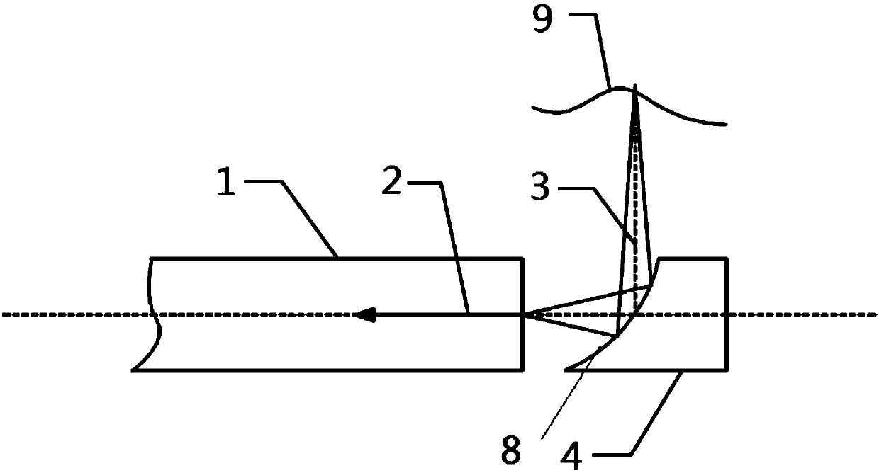
[0033] Such as figure 2 As shown, an endoscopic optical coherence tomography probe includes a single-mode optical fiber 1 , a focusing and beam turning member 4 with an integrated structure. A reflective surface is provided between the end of the single-mode optical fiber 1 and the focusing and beam turning member 4, the focusing and beam turning member 7 includes a beam turning surface 8, and the beam turning surface 8 or its cut surface is in contact with the single-mode fiber 1 The included angle between the axis lines of the single-mode fiber 1 is an acute angle; a small part of the light beam emitted by the single-mode fiber 1 is reflected by the reflective surface and returns to the original path to form a reference light 2, and the light beam emitted by the single-mode fiber 1 Most of the light is reflected on the beam turning surface 8 and then projected to the sample tissue 9 to be tested. The signal light returned from the sample tissue 9 is coupled into the probe s...

Embodiment 2

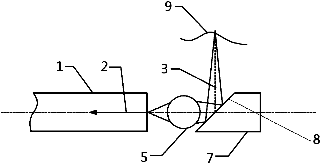
[0036] Such as image 3As shown, an endoscopic optical coherence tomography probe includes a single-mode optical fiber 1, a focusing lens 5 and a beam turning member 7, a gap is provided between the end of the single-mode optical fiber 1 and the focusing lens 5, and the There is a gap between the focusing lens 5 and the beam deflection member 7, the beam deflection member 7 includes a beam deflection surface 8, the angle between the beam deflection surface 8 or its cut surface and the axis of the single-mode optical fiber 1 is an acute angle; The single-mode optical fiber 1 and the beam turning member 7 are arranged coaxially. A small part of the light beam emitted by the single-mode optical fiber 1 is reflected and returned to the original path to form a reference light 2. Most of the light beam emitted by the single-mode optical fiber 1 is focused by the focusing lens 5 and then hits the beam turning surface 8 After upward reflection, it is projected to the sample tissue 9 ...

Embodiment 3

[0038] Such as Figure 4 As shown, an endoscopic optical coherence tomography probe includes a single-mode optical fiber 1, a focusing component 6 and a beam turning component 7, a gap is provided between the end of the single-mode optical fiber 1 and the focusing component 6, and the The focusing member 6 is fixedly connected with the beam turning member 7, and the focusing member 6 is located near the end of the single-mode optical fiber 1. The angle between the axis of the mode fiber 1 is an acute angle; the beam turning surface 8 is located at the end of the beam turning member 7, which faces the sample tissue 9; the single-mode fiber 1 and the beam turning member 7 are arranged coaxially. A small part of the light beam emitted by the single-mode optical fiber 1 is reflected and returns to the original path to form a reference light 2. Most of the light beam emitted by the single-mode optical fiber 1 is focused by the focusing member 6 and then hits the beam turning surfac...


PUM


Abstract

The present invention provides an endoscopic optical coherence tomographic imaging probe and an imaging system thereof. The endoscopic optical coherence tomographic imaging probe comprises a single mode optical fiber and a beam turning member. A reflective surface is arranged between the end of the single mode optical fiber and the beam turning member. The beam turning component comprises a beam turning surface, and the included angle of the beam turning surface or its cut surface and the axial line of the singlemode optical fiber is an acute angle.A small part of the light of the light beam emitted by the singlemode optical fiberis reflected bythe reflective surface and returns to the original path to form a reference light, most of the light of the light beam emitted by the singlemode optical fiberis reflected by the beam turning surface and cast onasample structure to be measured, and the signal light returned from the sample structure passes through the beam turning member, is coupled into the single mode optical fiber of the probe, and then merges with the reference light to form an interference light signal. With the above technical scheme, a reference arm shares the light path with a sample arm, and the entire light path system is simpler, more compact, and more reliable; and the quality and stability of images are improved.

Description

technical field [0001] The invention belongs to the technical field of medical devices, in particular to an endoscopic optical coherence tomography probe and an imaging system thereof. Background technique [0002] Since the invention of OCT (optical coherencetomography, optical coherence tomography) by Fujimoto and David Huang of MIT in 1991, the application of OCT in the medical field has developed rapidly, and the application in the field of ophthalmology is the most mature. In addition, in the Department of Cardiology In the fields of respiratory, gastroenterology, and urology, endoscopic OCT has the characteristics of shallow detection depth but high resolution, and forms a complementary relationship with ultrasonic endoscopy (deep detection depth and low resolution). Especially in cardiology For cardiovascular examination, endoscopic cardiovascular OCT has mature instruments and many clinical application cases, which largely makes up for the inability of IVUS (intraven...

Claims


Application Information

Patent Timeline
Patent Type & Authority Applications(China)
IPC IPC(8): A61B5/00A61B1/00A61B1/06
CPCA61B1/00165A61B1/00172A61B1/0661A61B5/0033A61B5/0066A61B5/0084
Inventor 白晓淞黄赞力
Owner INNERMEDICAL CO LTD
Why Eureka
Try Eureka