Oil-water-solid separation device for kitchen wastes

A technology of waste oil and oil-water separator, which is applied in the directions of liquid separation, separation method, grease/oily substance/floating matter removal device, etc., can solve the problem of unsatisfactory effect, deterioration and smell of kitchen waste, and consumption of a lot of energy. And other issues

Inactive Publication Date: 2012-08-22
卢瑞琳
View PDF4 Cites 16 Cited by
  • Summary
  • Abstract
  • Description
  • Claims
  • Application Information

AI Technical Summary

Problems solved by technology

[0007] The gutter oil problem has plagued the public for many years, but it remains unresolved. Up to now, governments around the world are formulating various governance policies and implementing pilot projects: although some cities have issued policies and regulations, they have not been implemented in time because the relevant supporting facilities cannot keep up; some The city’s environmental protection department implements special recycling and centralized treatment, but the effect is not satisfactory. Only a few restaurants and restaurants take the initiative to hand over swill to the sanitation department for disposal, and most of them sell it privately to farmers. Farmers regard it as a resource, and they have to pay high garbage disposal fees to the environmental sanitation department, and sell it to farmers for considerable profits; It is a well-developed catering industry. Since swill is a dirty and messy item, it is difficult to recruit workers. The staff of the above-mentioned enterprises are limited, and it is difficult to achieve daily cleanup. As a result, food and kitchen waste deteriorates, smells and smells, and becomes garbage in the real sense. Moreover, its collection, transportation and treatment process consumes a lot of energy, water resources, manpower and material resources, and causes secondary pollution.

Method used


Image

  • Oil-water-solid separation device for kitchen wastes
  • Oil-water-solid separation device for kitchen wastes
  • Oil-water-solid separation device for kitchen wastes

Examples


Embodiment Construction

[0025] The present invention will be further described below in conjunction with accompanying drawing of description:

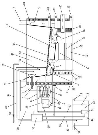
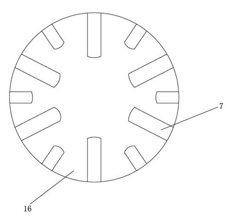
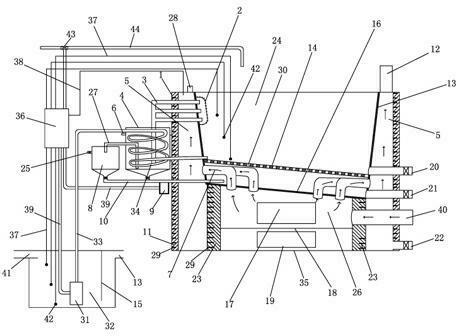
[0026] as attached figure 1 As shown, the kitchen waste oil-water-solid separation device of the present invention includes a heating furnace 35, an oil-water separator 4, a discharge port 20, a water outlet 21, a dust discharge port 22, an electric controller 36, and a grease trap 32. The heating furnace 35 is composed of a body of furnace 1 and a feed liquid container 24, the cavity between the body of furnace 1 and the feed liquid container 24 is a hot smoke chamber 5, and a chimney 12 is arranged on the top of the heat smoke chamber 5. The top of the liquid container 24 is provided with a spare water pipe 44, its bottom surface is a slope bottom 16, and its lower part is a high-temperature smoke chamber 26. A refractory support 23 is arranged around the high-temperature smoke chamber 26, and the middle part of the outer side is respectively provided with ...


PUM


Abstract

The invention discloses an oil-water-solid separation device for kitchen wastes, which comprises a heating furnace, an oil-water separator, a discharging port, a water outlet, a dust exhaust port, an electric controller, an oil separation tank and the like. The heating furnace consists of a furnace body and a feed liquid container, a cavity between the furnace body and the feed liquid container is a hot smoke chamber, a chimney is arranged at the top of the hot smoke chamber, a spare water pipe is arranged at the top of the feed liquid container with a slope bottom, and a high-temperature smoke chamber is arranged below the feed liquid container. Refractory supporting parts are arranged around the high-temperature smoke chamber, a flue inlet and a furnace opening are arranged in the outer middle of the high-temperature smoke chamber, a dust removal port is arranged below the furnace opening, a water material partition plate is arranged on the lower portion of the feed liquid container, a plurality of L-shaped smoke pipes communicated with the high-temperature smoke chamber and the hot smoke chamber are arranged below the water material partition plate, and an oil guide pipe is arranged on one side of the upper portion of the feed liquid container and communicated to the lower portion of the oil-water separator. The oil-water-solid separation device has the advantage of capabilities of using waste heat, removing smoke and dust, avoiding pan sticking, turning wastes into wealth and purifying environment.

Description

technical field [0001] The invention relates to equipment for heat treatment and separation of materials, in particular to an oil-water-solid separation device for kitchen waste. Background technique [0002] With the development of industrialization and urbanization and the improvement of people's living standards, the catering industry has entered an unprecedented heyday. At the same time, many sources of pollution such as kitchen waste heat, smoke and dust, oily sewage and grease-rich kitchen waste have been born. . [0003] Due to the small heat exchange area and short flue gas flow of kitchen stoves, the thermal efficiency is generally only 20-30%, and most of the heat sources have not yet had time to completely burn and exchange heat, and then turn into carbon black, toxic and harmful gases and waste heat (mainly carbon dioxide) It is exhausted from the chimney, causing serious pollution and waste. The waste heat of kitchen exhaust is generally as high as 200-300°C, a...

Claims


Application Information

Patent Timeline
Patent Type & Authority Applications(China)
IPC IPC(8): C02F9/10C02F1/40
Inventor 卢瑞琳
Owner 卢瑞琳
Why Eureka
Try Eureka