Direct type backlight source

A backlight and direct-type technology, which is applied in the field of direct-type backlights, can solve the problems of large thickness of direct-type backlights, and achieve the effects of reducing light mixing distance, reducing thickness, and increasing operating distance

Inactive Publication Date: 2012-08-22
BOE TECH GRP CO LTD +1
View PDF6 Cites 22 Cited by
  • Summary
  • Abstract
  • Description
  • Claims
  • Application Information

AI Technical Summary

Problems solved by technology

[0007] An embodiment of the present invention provides a direct-type backlight to so

Method used


Image

  • Direct type backlight source
  • Direct type backlight source
  • Direct type backlight source

Examples


Embodiment 1

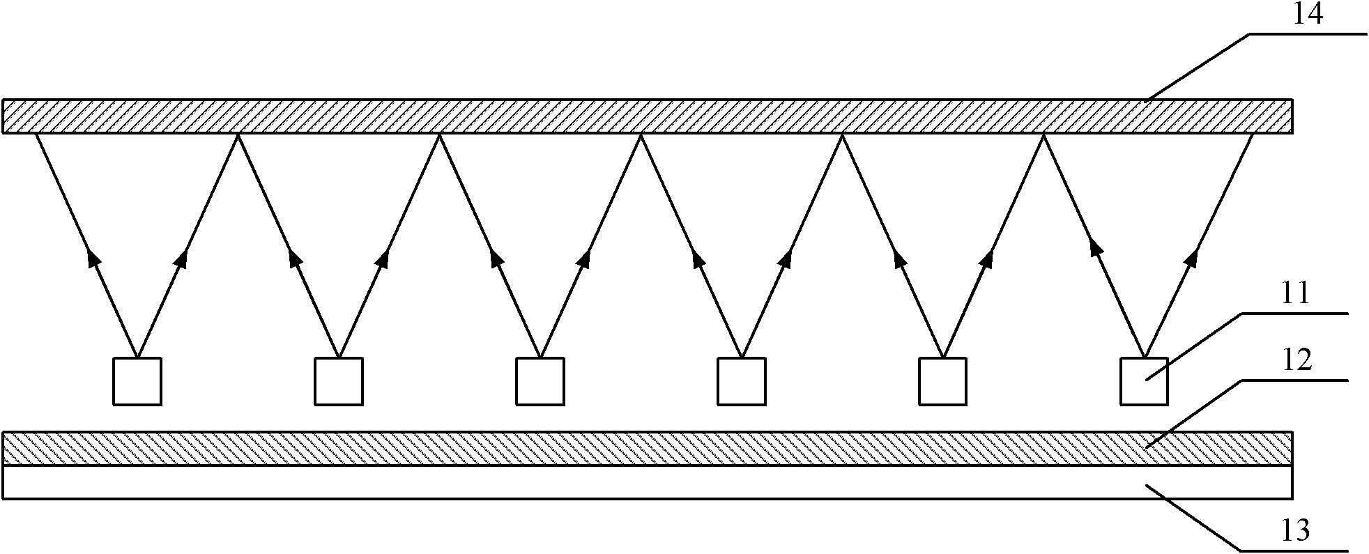
[0029] Embodiment 1 of the present invention provides a direct-lit backlight. The direct-lit backlight is provided with a semi-transparent and semi-reflective layer with a reflectivity greater than 0 and less than 1 between the diffuser and the illuminant. Part of the light emitted by the illuminant Multiple reflections are performed in the cavity formed by the transflective layer and the reflector to fully mix, which is equivalent to increasing the distance between the light diffuser and the illuminant, thereby reducing the thickness of the direct-type backlight. In turn, the thickness of the entire LCD is reduced.

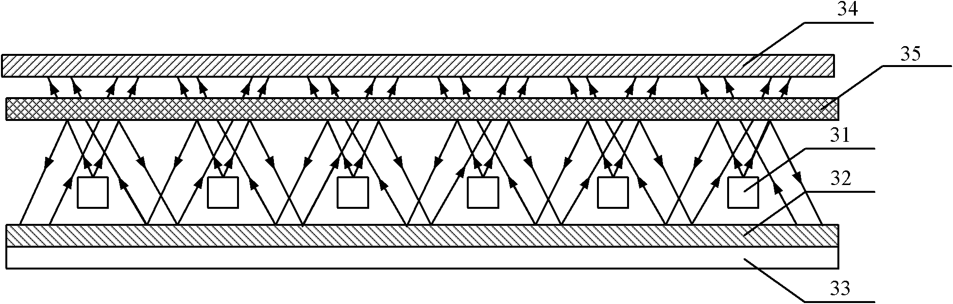
[0030] Such as image 3 As shown, it is a schematic diagram of the cross-sectional structure of the direct-lit backlight proposed in Embodiment 1 of the present invention, which includes several luminous bodies 31 arranged in parallel, a reflective sheet 32 ​​located below the luminous body 31 , and a back plate 33 located below the reflective sheet 32 , the dif...

Embodiment 2

[0048] Such as Figure 13 As shown, it is a schematic diagram of the cross-sectional structure of the direct-lit backlight proposed in Embodiment 2 of the present invention, including several luminous bodies 131 arranged in parallel, a reflective sheet 132 located below the luminous body 131, and a back plate 133 located below the reflective sheet 132 1. The diffusion plate 134 located above the illuminant 131 also includes a surface coating 135 coated on the lower surface of the diffusion plate 134, the surface coating 135 is partially coated on the lower surface of the diffusion plate 134, and the surface coating 135 includes Several coating microstructures in intervals, the reflectivity of the coating microstructures is 1.

[0049] Part of the light emitted by the illuminant 131 reaches the diffuser plate 134, and is output after being diffused by the diffuser plate 134. Then it reaches the diffuser plate 134 or the coating microstructure, so that part of the light emitted...


PUM


Abstract

The invention discloses a direct type backlight source comprising a light-emitting body, a reflection sheet located below the light-emitting body, a back plate located below the reflection sheet, and a diffusion plate located above the light-emitting body. The direct type backlight source further comprises a semi-transparent semi-reflecting layer arranged between the diffusion plate and the light-emitting body, wherein the reflection rate of the semi-transparent semi-reflecting layer is more than 0 and less than 1. With the adoption of the technical scheme, the thickness of the direct type backlight source is effectively reduced.

Description

technical field [0001] The invention relates to the technical field of liquid crystal display, in particular to a direct-lit backlight source. Background technique [0002] At present, in flat panel display (FPD, Flat Panel Display) technology, liquid crystal display (LCD, Liquid Crystal Display) has gradually replaced cathode ray tube display (CRT, Cathode Ray Tube). ), becoming the mainstream display. Since the LCD panel itself does not emit light, a light source must be added to the LCD panel to enable the LCD to display images, so the backlight is essential for the LCD. [0003] In the prior art, according to the different distribution positions of the backlight in the LCD, the backlight can be divided into two types: side-lit backlight and direct-lit backlight, wherein the side-lit backlight is placed on the side of the LCD display , The direct-type backlight is placed below the LCD display. The edge-lit backlight mainly converts light from a strip-shaped light sourc...

Claims


Application Information

Patent Timeline
IPC IPC(8): F21S8/00F21V5/08F21V7/22G02F1/13357
CPCG02F1/133603G02F1/133605G02F1/133611G02F1/1335
Inventor 应文涛
Owner BOE TECH GRP CO LTD
Why Eureka
Try Eureka