Absolute displacement measuring device

A technology of absolute displacement and absolute position, applied in measurement devices, optical devices, instruments, etc., can solve the problems of high cost of device customization, difficult signal processing, etc., to improve speed and acceleration performance, improve anti-pollution ability, simplify The effect of the readout circuit

Inactive Publication Date: 2012-08-22
CHANGCHUN INST OF OPTICS FINE MECHANICS & PHYSICS CHINESE ACAD OF SCI
View PDF4 Cites 41 Cited by
  • Summary
  • Abstract
  • Description
  • Claims
  • Application Information

AI Technical Summary

Problems solved by technology

[0005] The present invention provides an absolute displacement measuring device in order to solve the problems of high device customization cost and difficult signal processing in the existing absolute displacement measuring device

Method used


Image

  • Absolute displacement measuring device
  • Absolute displacement measuring device
  • Absolute displacement measuring device

Examples


specific Embodiment approach 1

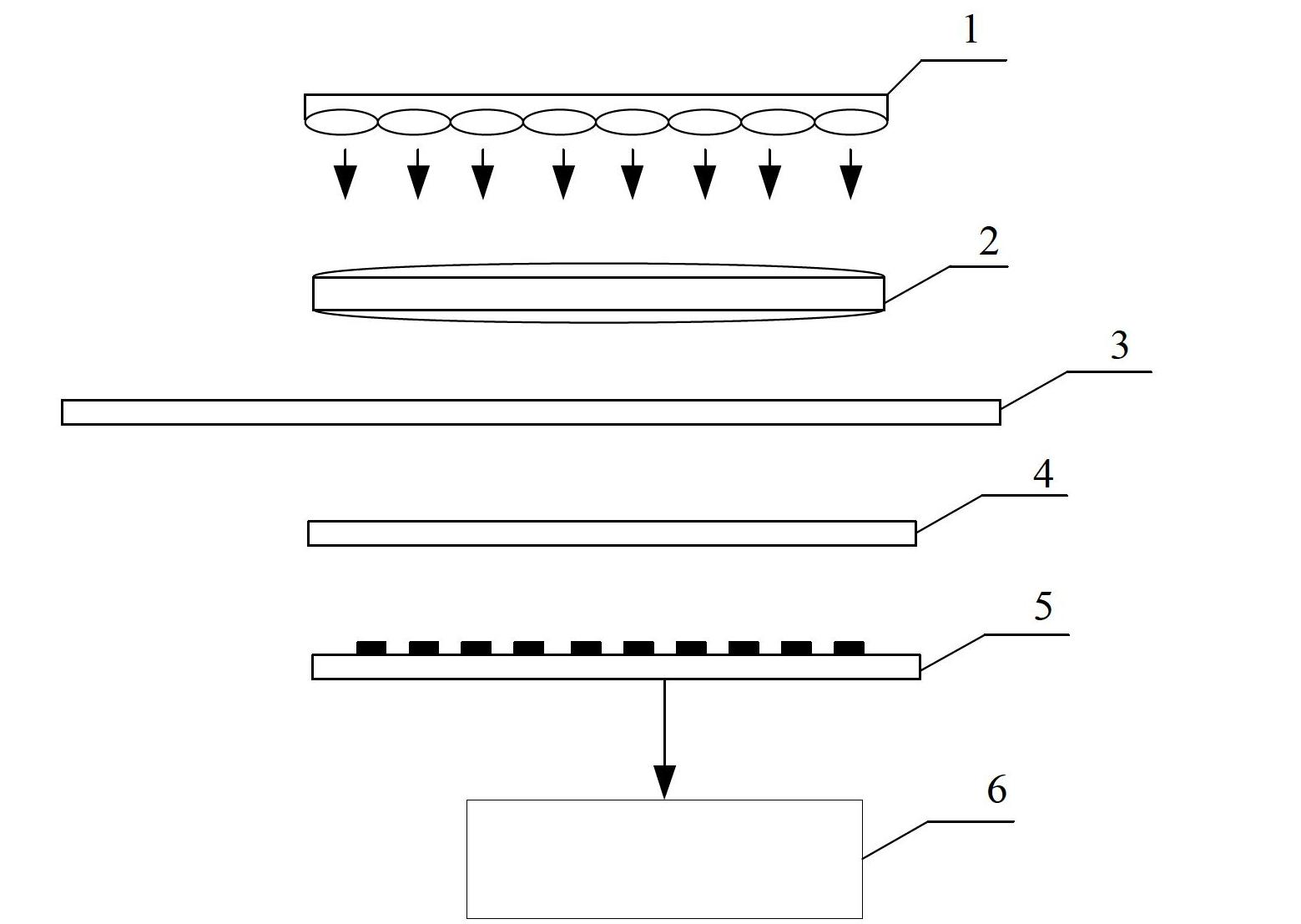
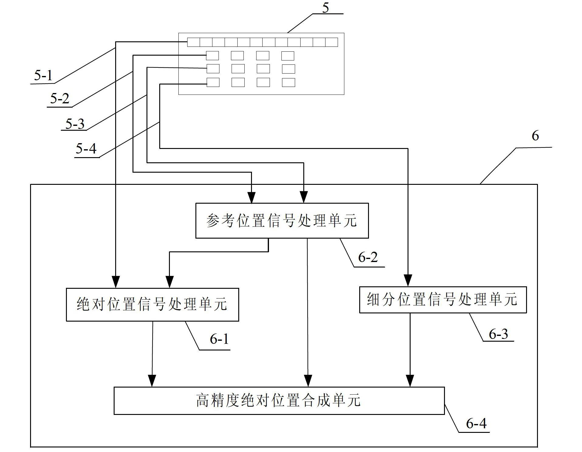
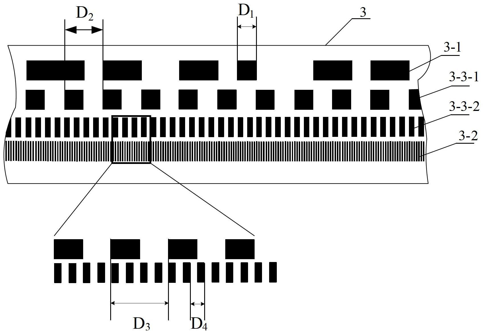
[0016] Specific implementation mode 1. Combination figure 1 and figure 2 Describe this embodiment, the absolute displacement measurement device, the device includes an absolute displacement measurement device, the device includes a light source 1, an optical system 2, a standard grating 3, a scanning mask 4, a photodetector 5 and a signal processing circuit 6, the standard The grating 3 includes an absolute code track 3-1, an incremental code track 3-2 and n reference code tracks 3-3; and an absolute code track 3-1, an incremental code track 3-2 and n reference code tracks 3-3 3 are arranged in parallel with each other, the absolute code track 3-1 contains a pattern of absolute position information, the incremental code track 3-2 includes the first light and dark stripes arranged along the measurement direction according to the first incremental cycle, and each reference code track 3-3 includes light and dark stripes arranged along the measurement direction according to an i...

specific Embodiment approach 2

[0027] Specific embodiment two, combine Figure 1 to Figure 7 Describe this implementation mode, this implementation mode is the embodiment of the absolute displacement measuring device described in specific implementation mode 1:

[0028] In this embodiment, the working process of the absolute displacement measuring device is described according to the fact that there are two reference code tracks, that is, the number of reference code tracks is expressed as n, and n is taken as 2, and the working mode in other cases where n is not 2 is essentially the same.

[0029] combine image 3 and Figure 4 , the standard grating 3 includes an absolute code track 3-1, a first reference code track 3-3-1, a second reference code track 3-3-2, and an incremental code track 3-2. The absolute code track 3 - 1 , the first reference code track 3 - 3 - 1 , the second reference code track 3 - 3 - 2 and the incremental code track 3 - 2 are arranged parallel to each other in a row. The incremen...


PUM


Abstract

The invention relates to an absolute displacement measuring device, which solves the problems of a high component customized cost and a large signal processing difficulty in prior absolute displacement measuring devices. The absolute displacement measuring device comprises a standard grating, a scanning mask, a light source, an optical system, a photoelectric detector and a signal processing circuit, wherein the standard grating further includes an incremental code channel, an absolute code channel and n reference position code channels, the incremental code channel includes first shading stripes arranged along a measuring direction according to a first incremental cycle, the absolute code channel comprises patterns which includes absolute position information and are arranged along the measuring direction, each of reference position code channels comprises the shading stripes arranged in the measuring direction according to an incremental cycle, and the cycle is longer than that of the incremental code channel. Light rays emitted by the light source are illuminated on the scanning mask through the optical system by the standard grating, and the photoelectric detector can receive an absolute position signal, a reference position signal and a subdivision signal. The signal processing circuit is used for processing an optical signal received by the photoelectric detector so as to obtain position values.

Description

technical field [0001] The invention relates to an absolute displacement measuring device, which is an accurate measuring instrument for measuring length. Background technique [0002] Grating displacement sensor is a position readout device commonly used in modern displacement measurement systems. It is widely used in the machine tool industry and other processing, manipulation and testing systems in the form of angle and length measurement devices. Its performance affects the quality of machining. [0003] At present, the known grating rulers of tools used to precisely measure the movement displacement of objects mainly include incremental and absolute. Among them, the absolute grating scale has gradually been widely used. Its main advantage is that it does not need to find the reference origin, and it can measure the position after the power is turned off. This is especially useful for systems that are difficult to return to zero. Therefore , which has a broad applicatio...

Claims


Application Information

Patent Timeline
Patent Type & Authority Applications(China)
IPC IPC(8): G01B11/02
Inventor 孙强张晓沛曾琪峰乔栋徐志军
Owner CHANGCHUN INST OF OPTICS FINE MECHANICS & PHYSICS CHINESE ACAD OF SCI
Why Eureka
Try Eureka