Miniaturized power gain balancer

A technology of power gain and equalizer, which is applied in the direction of the circuit components of the time-of-flight electronic tube and the introduction arrangement of the time-of-flight electronic tube. The effect of complexity, steep decay curve, and high Q value

Inactive Publication Date: 2012-08-22
UNIV OF ELECTRONICS SCI & TECH OF CHINA
View PDF4 Cites 7 Cited by
  • Summary
  • Abstract
  • Description
  • Claims
  • Application Information

AI Technical Summary

Problems solved by technology

[0003] For the microstrip line type, since the main transmission line and the resonant absorption unit are located in the same space layer, there is still room for further reduction in its volume, and the Q value of the resonant absorption unit is lower than that of the coaxial line or waveguide type. Not easy to achieve a steeper decay curve
[0004] For w

Method used


Image

  • Miniaturized power gain balancer
  • Miniaturized power gain balancer
  • Miniaturized power gain balancer

Examples


Embodiment Construction

[0026] Below in conjunction with accompanying drawing and specific embodiment, the present invention will be further described:

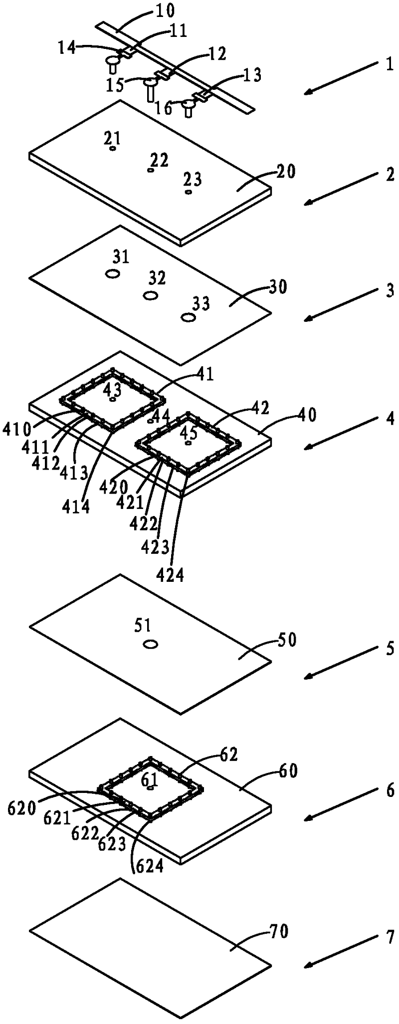
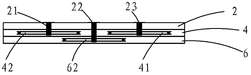
[0027] like figure 1 , figure 2 and image 3 As shown, a miniaturized power gain equalizer includes a microstrip layer 1, a first dielectric layer 2, a first metal layer 3, a second dielectric layer 4, a second metal layer 5, and The third dielectric layer 6 and the third metal layer 7;

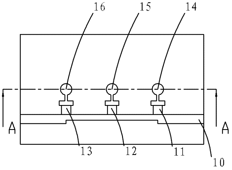
[0028] The microstrip layer 1 includes a transmission line main line 10, a first thin film resistor 11, a second thin film resistor 12, a third thin film resistor 13, a first metal connecting plate 14, a second metal connecting plate 15 and a third metal connecting plate 16, The first thin-film resistor 11, the second thin-film resistor 12, and the third thin-film resistor 13 are connected to the first metal connection plate 14, the second metal connection plate 15, and the third metal connection plate 16 respectively, and then arranged in sequence and connecte...


PUM


Abstract

The invention relates to a miniaturized power gain balancer, which comprises a micro-strip layer, a first medium layer, a first metal layer, a second medium layer, a second metal layer, a third medium layer and a third metal layer sequentially stacked from top to bottom. A first metalized through hole penetrates through a first via hole to be connected with a first metalized counter bore to form a probe structure, and the top of the probe structure is connected with a first metal connecting plate. A third metalized through hole penetrates through a third via hole to be connected with a second metalized counter bore to form a probe structure, and the top of the probe structure is connected with a third metal connecting plate. A second metalized through hole penetrates through a first via hole to be connected with a metalized through hole and then penetrates through a via hole to be connected with a metalized counter bore to form a probe structure, and the top of the probe structure is connected with a first metal connecting plate. The miniaturized power gain balancer has the advantages that a resonant cavity is embedded in a multi-layer medium substrate by the low-temperature co-fired ceramic technique, occupied planar space is reduced by a stereo staggered layer arrangement way, and miniaturization is realized.

Description

technical field [0001] The invention belongs to the technical field of power devices, and in particular relates to a power gain equalizer aimed at adjusting the flatness of power gain of a high-power traveling wave tube. Background technique [0002] At present, the commonly used power gain equalizers for adjusting the gain flatness of traveling wave tubes mainly include three types according to transmission line types: microstrip line type, waveguide type and coaxial line type. The basic composition of microstrip line type, waveguide type and coaxial line type includes a transmission line main line and several resonant absorption units connected to the transmission line main line. When the energy transmitted on the main line of the transmission line passes through a resonant absorbing unit, the resonant absorbing unit couples the resonant frequency of the resonant absorbing unit and a part of the energy around it into the resonant absorbing unit, relying on the absorbing me...

Claims


Application Information

Patent Timeline
IPC IPC(8): H01J23/20H01J23/14
Inventor 王志刚王欢延波徐锐敏
Owner UNIV OF ELECTRONICS SCI & TECH OF CHINA
Why Eureka
Try Eureka