
Distributed base station as well as data transmission method and device

A distributed base station and data technology, applied in electrical components, wireless communication, wireless network protocols, etc., can solve problems such as construction difficulties, lack, and degradation of baseband data processing performance, and achieve the effect of reducing data rate and bandwidth requirements.

Active Publication Date: 2012-08-22
CHINA MOBILE COMM GRP CO LTD
View PDF5 Cites 47 Cited by
  • Summary
  • Abstract
  • Description
  • Claims
  • Application Information

AI Technical Summary

Problems solved by technology

[0022] Depend on figure 1 It can be seen that the current distributed base station structure has the following disadvantages: the fiber interface between the BBU and the RRU requires high bandwidth, which makes it difficult and expensive to implement the fiber interface
However, since each antenna corresponds to one feeder cable, there are more feeder cables when there are many antennas, for example, at least 8 feeder cables are required for 8 antennas, which makes the construction very difficult
[0026] Another way to solve the above-mentioned shortcomings of the existing distributed base station is to move all the MAC sublayers in the BBU layer 2, or all the MAC sublayers and all the RLC sublayers, or the entire layer 2 to the RRU. However, this The solution of simply moving all sub-layers of layer 2 up to the RRU will cause degradation or loss of baseband data processing performance, for example, resulting in a decrease in real-time data processing or failure to meet the application requirements of subsequent evolution technologies, etc.

Method used


Image

  • Distributed base station as well as data transmission method and device
  • Distributed base station as well as data transmission method and device
  • Distributed base station as well as data transmission method and device

Examples


Embodiment Construction

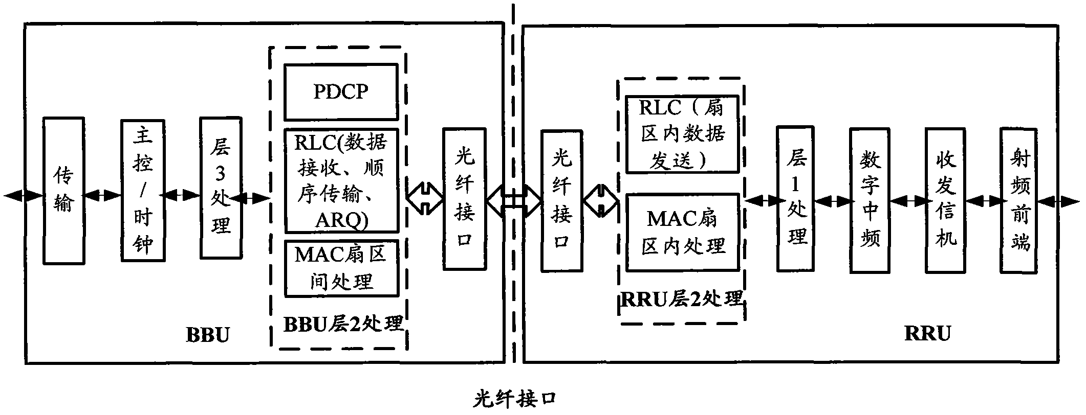
[0061] In the present invention, still considering the architecture based on BBU+RRU, a distributed base station architecture optimization scheme and implementation method are proposed, and the functions in BBU and RRU are re-divided: 1 (Physical layer) processing function is moved to RRU to significantly reduce the interface bandwidth between BBU and RRU, thereby effectively solving the problems of high bandwidth, difficult implementation and high cost of optical fiber interface between BBU and RRU. In current practical applications, Move all the processing functions of the physical layer to the RRU; on the other hand, put some of the processing functions of the layer 2 into the RRU, and put the remaining part of the processing functions of the layer 2 into the BBU. Specifically, by combining the The first part of the MAC sublayer data processing function and the first part of the RLC sublayer data processing function with a high coupling degree of physical layer data processi...


PUM


Abstract

The invention provides a distributed base station as well as a data transmission method and a data transmission device. The base station comprises a base band unit (BBU) and a radio remote unit (RRU) and is characterized in that the RRU comprises a first module and a second module, and the BBU comprises a third module, wherein the first module is used for carrying out data processing on a physical layer, the second module is used for carrying out data processing on the first part of MAC (Media Access Control) sublayer and data processing on the first part of RLC (Radio Link Control) sublayer, and the third module is used for carrying out data processing on the second part of MAC sublayer and data processing on the second part of RLC sublayer. After the invention is applied, the bandwidth requirement on a fiber interface between the BBU and the RRU in the base station can be lowered, and meanwhile, the processing performance of baseband data is ensured.

Description

technical field [0001] The present invention relates to the technical field of wireless communication, in particular to a distributed base station, a data transmission method and a device. Background technique [0002] The existing long-term evolution (Long Term Evolution, LTE) distributed base station architecture divides the entire base station into two parts: a baseband unit (BBU) and a remote radio unit (RRU). For details, see figure 1 . [0003] figure 1 It is a structural diagram of an existing distributed base station. [0004] Such as figure 1 As shown, in the existing distributed base station, the BBU includes a transmission interface module, a main control / clock module, a baseband processing module and an optical fiber interface module. RRU includes optical fiber interface module, digital intermediate frequency module, transceiver module and radio frequency front-end module. [0005] Among them, each module of the BBU mainly completes the following functions: ...

Claims


Application Information

Patent Timeline
IPC IPC(8): H04W80/02H04W88/08
Inventor 许灵军邓伟王东程广辉
Owner CHINA MOBILE COMM GRP CO LTD
Learn More