
Electron linear accelerator having dual purposes and dual-purpose method of electron linear accelerator

A linear accelerator and dual-purpose technology, applied in the direction of linear accelerators, electrical components, accelerators, etc., can solve the problems of increased costs, limited use of accelerators, and no large-scale promotion, and achieve the effect of broadening the application field and saving costs

Inactive Publication Date: 2012-08-22
HARBIN ENG UNIV
View PDF14 Cites 9 Cited by
  • Summary
  • Abstract
  • Description
  • Claims
  • Application Information

AI Technical Summary

Problems solved by technology

However, in the case that the user needs to implement two applications of electron irradiation and radiography, if the above-mentioned accelerator application design is used, the user needs to purchase two independent accelerator devices to realize different functions respectively, which will greatly increase the cost
[0003] In recent years, in the field of medical imaging, electron accelerators with adjustable energy have been realized, and electron beams with different energies can be used to achieve different functions. However, the use of this accelerator is still very limited and has not been widely promoted.

Method used


Image

  • Electron linear accelerator having dual purposes and dual-purpose method of electron linear accelerator
  • Electron linear accelerator having dual purposes and dual-purpose method of electron linear accelerator
  • Electron linear accelerator having dual purposes and dual-purpose method of electron linear accelerator

Examples


specific Embodiment approach 1

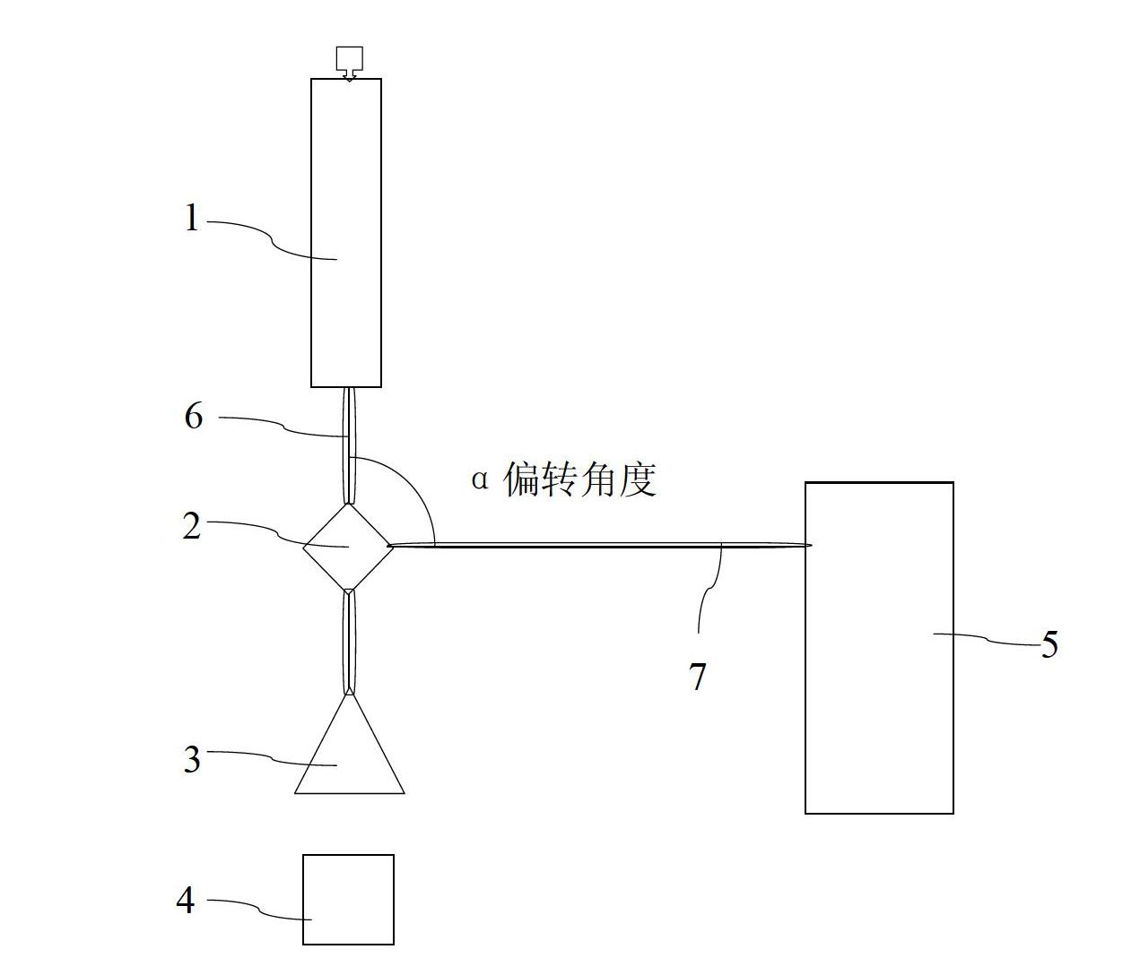
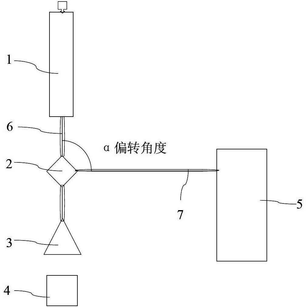
[0023] to combine figure 1 , the structure of the standing type one-machine dual-purpose electron linear accelerator is as follows: including an accelerating tube 1, a scanning box 3, an industrial CT5, and a beam deflection system; the beam deflection system includes a front quadrupole magnet 6 behind the accelerating tube 1, The deflection magnet 2 behind the front quadrupole magnet 6, the rear quadrupole magnet 7 and the scanning magnet behind the deflection magnet 2; the industrial CT5 is behind the rear quadrupole magnet 7, and the scanning box 3 is behind the scanning magnet; the acceleration tube 1 is vertically arranged , the front quadrupole magnet 6, the scanning magnet and the scanning box 3 are arranged vertically.

[0024] The electron beam is provided by the electron gun, and interacts with the radio frequency electric field in the accelerating tube 1 to obtain energy. The electron beam from the accelerating tube is focused by the quadrupole magnet 6 and enters t...

specific Embodiment approach 2

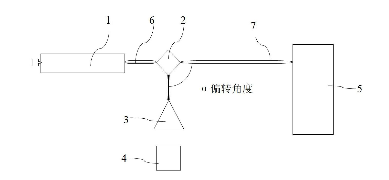
[0025] to combine figure 2 , the structure of the horizontal and vertical one-machine dual-purpose electron linear accelerator is as follows: including an accelerating tube 1, a scanning box 3, an industrial CT5, and a beam deflection system; the beam deflection system includes a front quadrupole magnet 6 positioned behind the accelerating tube 1 , the deflection magnet 2 behind the front quadrupole magnet 6, the rear quadrupole magnet 7 and the scanning magnet behind the deflection magnet 2; the industrial CT5 is behind the rear quadrupole magnet 7, and the scanning box 3 is behind the scanning magnet; the acceleration tube 1 is horizontal For setting, the front quadrupole magnet 6, the rear quadrupole magnet 7 and the industrial CT5 are arranged horizontally.

[0026] The electron beam advances horizontally in the accelerator tube 1 to obtain energy, and is focused by the quadrupole lens 6 and enters the deflection magnet 2. When the deflection magnet 2 is turned off, the a...


PUM


Abstract

Disclosed is an electron linear accelerator having dual purposes and a dual-purpose method of the electron linear accelerator. The electron linear accelerator comprises an accelerating tube, a scanning box, an industrial computed tomography (CT) and a beam deflection system, wherein the beam deflection system comprises a front quadrupole magnet, a deflection magnet, a rear quadrupole magnet and a scanning magnet; the front quadrupole magnet is arranged behind the accelerating tube, the deflection magnet is arranged behind the front quadrupole magnet, and the rear quadrupole magnet and the scanning magnet are arranged behind the deflection magnet; the industrial CT is arranged behind the rear quadrupole magnet and the scanning box is arranged behind the scanning magnet; and the deflection magnet is controlled to be opened or closed, and electronic beam current is selected for moving forwards in a linear mode or for deflecting at an alpha angle, so that the electronic beam current selectively enters the scanning box or the industrial CT. The electron linear accelerator having dual purposes and the dual-purpose method of the electron linear accelerator solve the problem that the requirements of dual purposes on electron beam spot sizes are contradictory. Under the condition that all performances meet the requirements, the cost is reduced. The electron linear accelerator having dual purposes and the dual-purpose method of the electron linear accelerator not only perform electron beam irradiation by using different energy but also generate X rays with different energy, and perform CT imaging.

Description

technical field [0001] The present invention relates to an electron accelerator. The invention also relates to an application method of the electron linear accelerator. Background technique [0002] At present, in the application of electron linear accelerators, each accelerator generally can only realize one function, which is electron irradiation or X-ray imaging. Electron irradiation plays an important role in the fields of material modification, radiation sterilization, and food preservation, and X-ray imaging plays an irreplaceable role in nondestructive testing, medical diagnosis, and security inspection. When electron beams are used to irradiate items, the electron beam spot is required to be relatively large and the beam current is relatively uniform. Through the action of the scanning magnet and the item conveyor belt, the scanning of the items can be realized. When using X-ray imaging, in order to achieve higher spatial resolution and image clarity, it is require...

Claims


Application Information

Patent Timeline
IPC IPC(8): H05H9/00
Inventor 李桃生王国保唐鄂生宫存溃刘春雨颜强王庆宇张志俭夏虹李忠宇
Owner HARBIN ENG UNIV
Learn More