Accelerator pedal system with tension trigger switch for correcting wrong use of accelerator as brake
A technology of accelerator pedal and trigger switch, which is applied in the direction of brake safety system, vehicle components, engine control, etc., and can solve problems such as difficult installation, unfavorable prevention of car accidents, and large volume
- Summary
- Abstract
- Description
- Claims
- Application Information
AI Technical Summary
Problems solved by technology
Method used
Image
Examples
Embodiment 1
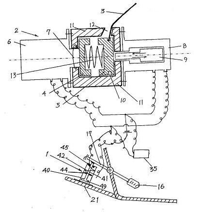
[0049] Embodiment 1. A tension trigger switch is installed between the accelerator pedal connecting rod and the vehicle body. An accelerator pedal system with a tension trigger switch for correcting misstepping on the accelerator
[0050] Such as figure 1 ,
[0051] [1] Pull trigger switch: a cylindrical shell 40 is provided with a movable rod 41 and a spring 42; one end of the movable rod 41 is fixed with a "T"-shaped compression spring which is slightly smaller than the inner space of the shell 40 and can slide freely The plate 49, the compression spring plate 49 is located at the bottom end of the housing 40, the center post of the moving rod 41 extends out of the hole at the top of the housing 40; an electrical contact fixing ring 45 is fixed on the inner wall of the top of the housing 40, and the compression spring plate 49 is in electrical contact The middle part of the moving rod 41 between the fixed rings 45 is covered with an electric contact sliding ring 44 that can slide...
Embodiment 2
[0061] Embodiment 2. A tension trigger switch is provided between the accelerator pedal connecting rod and the vehicle body. An accelerator pedal system with a tension trigger switch for correcting misstepping on the accelerator
[0062] [1] Pull trigger switch: the same as in Example 1.
[0063] [2] The setting position of the switch: Set the pull trigger switch 1 between the accelerator pedal linkage 17 and the vehicle body part 21. The housing 40 of the switch 1 with pull force is fixed on the vehicle body part 21 above the accelerator pedal connecting rod 17, and the center post of the moving rod 41 extending out of the hole of the housing 40 is connected with the accelerator pedal connecting rod 17 by pulling force trigger switch 1. When the accelerator pedal 16 is not stressed, the spring 42 makes the compression spring plate 49 located at the bottom of the housing 40. When the accelerator pedal 16 is stressed, the accelerator pedal link 17 moves away from the pull trigger sw...
PUM
 Abstract
Description
Claims
Application Information
 - R&D
- Intellectual Property
- Life Sciences
- Materials
- Tech Scout
- Unparalleled Data Quality
- Higher Quality Content
- 60% Fewer Hallucinations
Browse by: Latest US Patents, China's latest patents, Technical Efficacy Thesaurus, Application Domain, Technology Topic, Popular Technical Reports.
© 2025 PatSnap. All rights reserved.Legal|Privacy policy|Modern Slavery Act Transparency Statement|Sitemap|About US| Contact US: help@patsnap.com


