Pressure-triggered switch type accelerator pedal system for preventing accelerator from being used as brake

A trigger switch, accelerator pedal technology, applied in the direction of brake safety system, vehicle components, engine control, etc., can solve the problems of complex structure, long wrong travel, difficult installation, etc.

Inactive Publication Date: 2012-08-29
ZHEJIANG XIANAN AUTOMOBILE BREAKING SYST
View PDF11 Cites 7 Cited by
  • Summary
  • Abstract
  • Description
  • Claims
  • Application Information

AI Technical Summary

Problems solved by technology

The first disadvantage of this technology is that in the continuously changing pressure signal felt by the annunciator, when the signal acquisition device for judging and taking out the false accelerator pedal signal is faulty, it may make an error in the judgment of the false accelerator pedal signal, resulting in the failure of the system. poor reliability
The second disadvantage of this technology is to use the signal output line to control the electric valve, and use the electric valve to shut off the engine oil supply pipe, ignition circuit, motor power supply, etc. of the vehicle, so that the driver has a long time to step on the accelerator by mistake until the vehicle is stopped. The wrong trip is far away, and this slow response is not conducive to preventing car accidents from happening
The third disadvantage of this technology is to use the signal output line to control the electric valve, and use the electric valve to cut off the engine oil supply pipe, ignition circuit, motor power supply, etc. of the vehicle, so that the engine will stop rotating and work completely, causing the brake system and steering of the car to be damaged. system, anti-skid and other safety systems have all stopped working, so shutting off the engine of the vehicle with a false accelerator pedal signal is not conducive to performing error-correcting emergency braking when there is a false accelerator pedal
[0003] In his patent application 201110030092.4 "A Device for Automatically Correcting Misstepped Accelerators to Brakes with the Coordination of Electric Appliances and Machinery", the applicant disclosed a device including sensors and signal analyzers And the device of the brake starting mechanism, its disadvantages are that there are many microelectronic devices to obtain the signal of the accelerator pedal by mistake, and the reliability is reduced; the disadvantage is that in the brake starting mechanism, the circular motion of the motor is changed For reciprocating motion, the straight rack is used to change the motion mode, because to ensure the reciprocating motion of the straight rack positioning, it is necessary to have a frame that fixes the relative position of the motor and the straight rack. This frame is bulky and it is difficult to find a suitable position. installation, and complex structure, high cost and poor reliability

Method used


Image

  • Pressure-triggered switch type accelerator pedal system for preventing accelerator from being used as brake
  • Pressure-triggered switch type accelerator pedal system for preventing accelerator from being used as brake
  • Pressure-triggered switch type accelerator pedal system for preventing accelerator from being used as brake

Examples


Embodiment 1

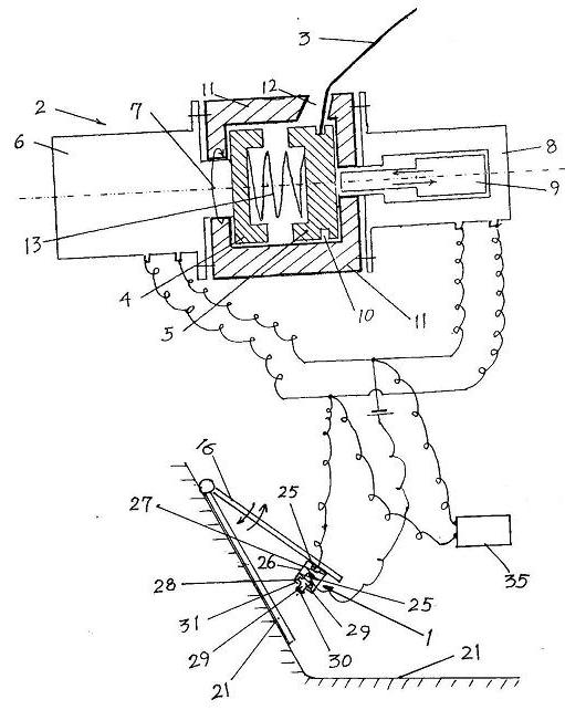
[0057] Embodiment 1. The spring-type pressure trigger switch is located on the back of the accelerator pedal, and the gas pedal system with pressure trigger switch is used for correcting the wrong step on the accelerator.

[0058] like figure 1 , 4 , 5, 6,

[0059] [1] The structure of the switch: the structure of the pressure trigger switch 1 of this embodiment is that the spring type pressure trigger switch 1 includes a sliding cylinder 26, an inner hollow coil spring 27, a cross-shaped piston 28 and two conductive contacts 25; Type coil spring 27 is located among the slide tube 26, and the two ends of hollow type coil spring 27 contact the bottom of slide tube 26 and the piston disc of cross-shaped piston 28 respectively; At the top, one section of the middle post 29 of the cross-shaped piston 28 stretches out from the middle hole of the top cover 31 of the middle hole in the sliding cylinder 26. The other section of 29 is located in the coil of the hollow coil spring 27...

Embodiment 2

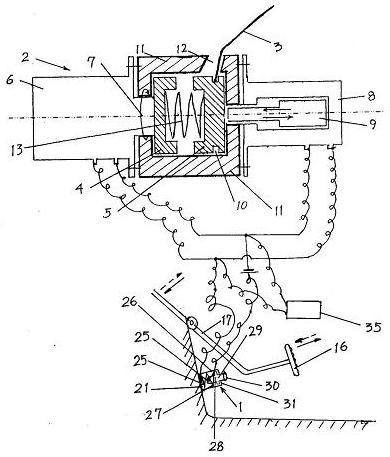
[0070] Embodiment 2. The spring-type pressure trigger switch 1 is located at the corresponding car body part on the back of the accelerator pedal, and the gas pedal system with pressure trigger switch is used for correcting the wrong step on the accelerator.

[0071] [1] The structure of the switch: the same as in Embodiment 1.

[0072][2] The setting position of the switch: set the spring-type pressure trigger switch 1 on the corresponding vehicle body part 21 on the back of the accelerator pedal 16, so that the force-bearing block 30 of the spring-type pressure trigger switch 1 faces the back of the accelerator pedal 16, and the force-bearing block The space distance between 30 and the back side of gas pedal 16 will satisfy when the power of foot stepping on gas pedal 16 is less than 8 kilograms, and the back side of force block 30 and gas pedal 16 does not contact, and gas pedal is normally refueled and improves the vehicle speed. Only when the power of stepping on the acce...

Embodiment 3

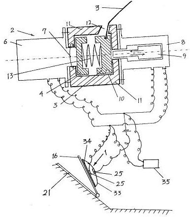
[0075] Embodiment 3. The spring-type pressure trigger switch 1 is set on the gas pedal connecting rod to correct the accelerator pedal system with a pressure trigger switch for correcting the wrong step on the gas pedal.

[0076] [1] The structure of the switch: the same as in Embodiment 1.

[0077] [2] The setting position of the switch: the spring-type pressure trigger switch 1 is set on the back of the accelerator pedal connecting rod 17, the force-bearing block 30 of the spring-type pressure trigger switch 1 faces the corresponding vehicle body part 21, and the force-bearing block 30 is aligned with the corresponding vehicle body part 21. The space distance between the body parts 21 will satisfy when the power of stepping on the accelerator pedal 16 is less than 8 kilograms, the stressed block 30 does not contact with the corresponding car body parts 21, so that the accelerator is normally refueled to increase the speed of the vehicle. Only when the power of stepping on th...


PUM


Abstract

The invention relates to a pressure-triggered switch type accelerator pedal system for preventing an accelerator from being used as a brake, which belongs to an accelerator system capable of directly acquiring a false accelerator stepping signal. A pressure-triggered switch is arranged on the front or back of an accelerator pedal or on a body part corresponding to the accelerator pedal, and the pressure-triggered switch is a switch which enables two conductive contacts to be in contact with each other to conduct electricity after an elastic element in the switch is deformed by switch threshold pressure, the position where the pressure-triggered switch is arranged ensures that a switch threshold corresponds to a false stepping threshold, and the pressure-triggered switch is connected with a trigger signal converter. The pressure-triggered switch type accelerator pedal system has the advantages that: the pressure-triggered switch type accelerator pedal system can directly acquire the false accelerator stepping signal, and does not need a pressure sensor with a microelectronic circuit to analyze accelerator stepping acts with different weights to find out false accelerator stepping acts, the response of the system is quick, the structure is simple, the cost is low, the size is small, and the system is easy to mount, and is a highly-reliable accelerator system which can directly acquire the false accelerator stepping signal.

Description

technical field [0001] The invention belongs to the technical field of automobile accelerator systems, in particular to an accelerator system capable of directly obtaining a signal of a false accelerator pedal, which can convert the action of a false accelerator pedal into an accelerator device for driving a brake mechanism. Background technique [0002] In his authorized patent 20051001077.X "throttle system device with annunciator", the applicant provides a device that determines whether to remedy the brake after judging whether the throttle action is correct or wrong, so that the throttle can be The utility model relates to a dual-purpose motor vehicle gas pedal system which can be used for braking and accelerating. It is characterized in that an annunciator is arranged on any one of the accelerator pedal, the linkage device, and the accelerator pedal corresponding to the vehicle body parts. The annunciator is connected with the electric valve that can cut off the oil ci...

Claims


Application Information

Patent Timeline
Patent Type & Authority Applications(China)
IPC IPC(8): B60K26/02B60T7/04
CPCB60T7/042B60T17/18B60T17/221B60W50/087B60W50/10F02D11/02
Inventor 颜昌松
Owner ZHEJIANG XIANAN AUTOMOBILE BREAKING SYST
Why Eureka
Try Eureka