Multi-alloy step feed device for metallurgy smelting

A multi-alloy and metallurgical technology, applied in the field of metallurgical smelting multi-alloy step-by-step adding devices, can solve the problems of large equipment investment, complex production process and high maintenance cost, and achieve the effects of reducing production cost, simplifying adding process and reducing labor intensity.

Active Publication Date: 2013-08-07
LONGNAN LONGYI HEAVY RARE EARTH TECH CO LTD
View PDF3 Cites 0 Cited by
  • Summary
  • Abstract
  • Description
  • Claims
  • Application Information

AI Technical Summary

Problems solved by technology

The wire feeding method is to first crush the deoxidized, desulfurized or purified alloy into powder, and then roll it into a round wire on the cored wire unit with a steel belt. The production process is complicated and the cost is high. Special wire feeding equipment requires a large investment in equipment and high maintenance costs; while using the flushing method, the addition of a large amount of purification is difficult to control, and the absorption rate of effective elements in the alloy is low
[0003] When multiple alloys need to be added in a certain order, the common method is to add an alloy at the bottom of the steel (iron) ladle first, then add a part with the flow when the molten iron is tapped, and then add the remaining alloy after the molten iron is tapped. The method is not easy to control, especially the alloy added with the flow and the alloy added after the molten iron is discharged are easy to float on the surface of the molten iron and oxidize in contact with the air. The effective element absorption rate of the alloy is low, which affects the effect.

Method used


Image

  • Multi-alloy step feed device for metallurgy smelting
  • Multi-alloy step feed device for metallurgy smelting

Examples


Embodiment Construction

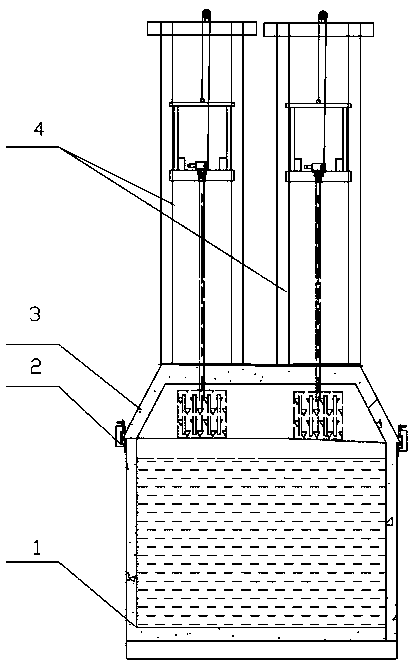
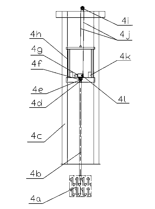
[0014] A multi-alloy step-by-step adding device for metallurgical smelting, in which more than two alloy feeders 4 are arranged on the cover 3 of the ladle 1, the cover 3 and the ladle 1 are fixed by a connecting card 2, and the alloy feeder 4 includes a bracket 4c , the carriage 4h is installed in the bracket 4c, the double output shaft belt motor speed reducer 4g and the counterweight iron 4k are arranged on the carriage 4h, and the lifting wheel 4l is installed on one of the output shafts of the double output shaft belt motor speed reducer 4g, and the other An electromagnetic clutch device 4f is installed on an output shaft, and the steel wire rope 4j is sleeved on the guide wheel assembly 4i on the top of the bracket 4c, one end of which is connected with the carriage 4h, and the other end is connected with the lifting wheel 4l, and the alloy frame 4a is fixed to the connecting rod 4b. Then, the upper end of the connecting rod 4b is connected with the shaft sleeve 4e fixed ...


PUM


Abstract

The invention discloses a multi-alloy step feed device for metallurgy smelting. More than two alloy feeders are arranged on a ladle cover of a ladle; each of the alloy feeders comprises a bracket; a sliding frame is mounted in the bracket; a dual-output shaft belt motor reducer and counterweight iron are arranged on the sliding frame; a lifting wheel is mounted on one output shaft of the dual-output shaft belt motor reducer, and an electromagnetic clutch device is mounted on the other output shaft of the dual-output shaft belt motor reducer; a steel wire rope is sleeved onto a guide wheel assembly at the top of the bracket, and one end of the steel wire rope is connected with the sliding frame while the other end of the steel wire rope is connected with the lifting wheel; and an alloy frame is connected with a shaft sleeve fixed onto the electromagnetic clutch device through a connecting rod and a bolt. According to the multi-alloy step feed device for metallurgy smelting, the alloys are directly pressed into molten steel through a pressing-in device, are directly molten in the molten steel and cannot contact air so as to avoid oxidization and burning loss; the feeding amount of the alloys can be reduced while the absorption rate is greatly increased, so that the production cost is favorably reduced and the absorption and component uniformity of the alloys in the molten steel are improved at the same time; and the feeding process is simplified and the labor intensity is reduced.

Description

technical field [0001] The invention relates to a multi-alloy step-by-step adding device for metallurgical smelting. Background technique [0002] Nowadays, alloys such as calcium, barium, manganese, and magnesium are usually used as purifying agents to deoxidize and desulfurize steel to improve its performance. The method of adding purified alloys is generally the wire feeding method and the flushing method. The wire feeding method is to first crush the deoxidized, desulfurized or purified alloy into powder, and then roll it into a round wire on the cored wire unit with a steel belt. The production process is complicated and the cost is high. Special wire feeding equipment requires a large investment in equipment and high maintenance costs; while using the flushing method, the addition of a large amount of purification is difficult to control, and the effective element absorption rate of the alloy is low. [0003] When multiple alloys need to be added in a certain order, t...

Claims


Application Information

Patent Timeline
Patent Type & Authority Patents(China)
IPC IPC(8): C21C7/04
Inventor 廖志金朱福生刘燕平杨清钟伟昌杨宇鹏
Owner LONGNAN LONGYI HEAVY RARE EARTH TECH CO LTD
Why Eureka
Try Eureka