
Technical scheme of intermittent inflating turbine engine

A technology of turbine engine and technical solution, which is applied to engine components, gas turbine devices, machines/engines, etc., can solve the problems of restricting the bypass ratio and thrust-weight ratio of the engine, high outlet temperature of the gas turbine engine, and low thermal energy utilization efficiency. The effect of long service life, simple structure and improved thermal energy utilization efficiency

Inactive Publication Date: 2012-09-05
周耀瑜
View PDF0 Cites 1 Cited by
  • Summary
  • Abstract
  • Description
  • Claims
  • Application Information

AI Technical Summary

Problems solved by technology

Secondly, the outlet temperature of the gas turbine engine is very high, and the efficiency of heat energy utilization is low; in order to make the gas flow in one direction, high-pressure air must be continuously pressed into the combustion chamber, and there is a phenomenon of pressure loss. The engine structure is still relatively complicated, and the fuselage is long. Heavy weight severely restricts the bypass ratio and thrust-to-weight ratio of the engine

Method used


Image

  • Technical scheme of intermittent inflating turbine engine
  • Technical scheme of intermittent inflating turbine engine
  • Technical scheme of intermittent inflating turbine engine

Examples


Embodiment Construction

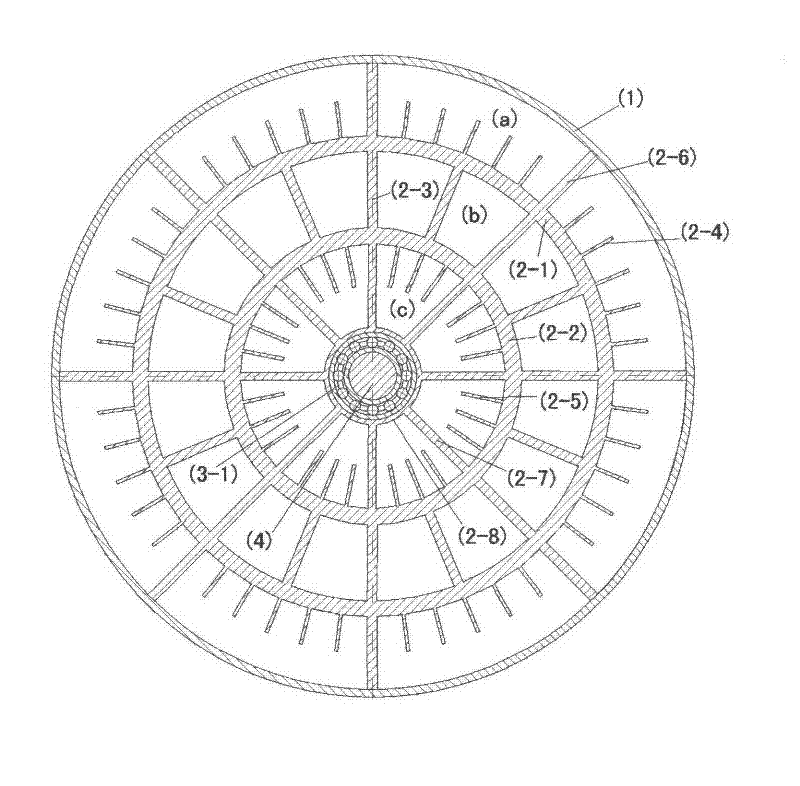
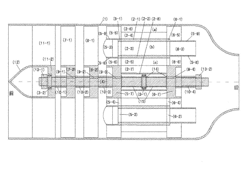
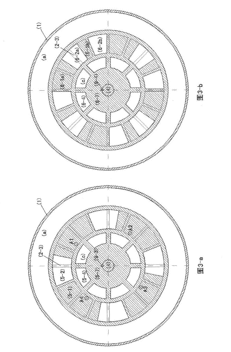
[0051] 1, the design of the combustion chamber stator (2) and the front and rear end covers (5, 6) of the combustion chamber is the technical core of the engine of the present invention. During the design process, it must be ensured that the combustion chamber has the characteristics of intermittent cycle ramming and ventilation and ignition work, that is, to ensure that the front and rear two functional end covers and the working state of the combustion chamber must have two most fundamental correspondences:

[0052] (1) Open - open - press ventilation;

[0053] (2) sealing - opening - ignition work.

[0054] The design steps of the combustion chamber stator and the front and rear end covers of the combustion chamber:

[0055] (1) Firstly, consider the application of starting, determine the output power of the engine and determine the corresponding relationship between the appropriate front and rear end covers and the combustion chamber, and find the working cycle T.

[005...


PUM


Abstract

The invention provides a technical scheme of an intermittent inflating turbine engine. The type of engine mainly comprises a ring-body-shaped combustion chamber stator, a front functional end cover (rotor) and a rear functional end cover (rotor), wherein the ring-body-shaped combustion chamber stator is formed by a plurality of integral combustion chambers which are arranged into a ring and are same in shape and dimension, and the two functional end covers (rotors) rotate synchronously. During the operation process, when the front and rear parts of the combustion chamber are open, the combustion chamber is pressurized and ventilated, when oil mixing and ignition are carried out in the combustion chambers, the front end of the combustion chamber is sealed by the front end cover, thus a turbine blade behind the combustion chamber is pushed to rotate and do wok by utilizing high-pressure fuel gas efficiently; from the point of view of the whole engine, the engine pushes the turbine blade to rotate and do work by utilizing the high-pressure fuel gas continuously; from the point of view of certain combustion chamber, the combustion chamber has the characteristic of intermittent and cycle operation; the technical scheme of the intermittent inflating turbine engine is suitable for all occasions with easy flowing fuel materials which are combusted by virtue of air, and is widely applied to all mechanical motive power devices, is simple in structure, is low in operating temperature of the engine body, is short in engine body, is light in weight, is high in fuel oil power efficiency, and obtains high bypass ratio and thrust-weight ratio.

Description

Technical field [0001] The invention provides a new type of intermittent impingement turbine engine technical scheme, the engine is mainly composed of a combustion chamber stator formed by a plurality of circularly arranged whole-body combustion chambers with the same shape and size, and two front and rear synchronously rotating functional end covers (rotors) ) and other components. During the working process of the engine, the combustion chamber is rammed and ventilated when both the front and rear of the combustion chamber are in an open state. When oil is mixed and ignited in the combustion chamber, the front end cover seals the front end of the combustion chamber, thereby efficiently using high-pressure gas to drive After the combustion chamber, the turbine blades rotate to do work. The engine of the invention is suitable for all occasions that rely on air to combust easily flowing fuel, and is widely used in various mechanical power devices, such as various aviation equi...

Claims


Application Information

Patent Timeline
IPC IPC(8): F02C3/14F02C3/04F02C7/22F02C7/00F23R3/42
Inventor 周耀瑜
Owner 周耀瑜
Learn More