Jet pump

A technology of ejector pumps and components, applied in the field of ejector pumps, can solve the problem of reducing the approximate ejection ratio or pumping capacity of jet pumps, reducing the ability of primary fluid to pump secondary fluid, axial size, and large space occupation weight and other problems, to achieve the effect of increasing mutual ejection and secondary mixing functions, a wide range of uses, and solving low ejection efficiency

Inactive Publication Date: 2012-09-05
韩铁夫
View PDF8 Cites 18 Cited by
  • Summary
  • Abstract
  • Description
  • Claims
  • Application Information

AI Technical Summary

Problems solved by technology

Because of the occlusion of the surrounding streams or peripheral jet beams, it is difficult for the surrounding secondary fluid to be drawn into the inner area of ​​the central jet, and the entrainment is still mainly carried out around the mixing chamber, which will inevitably reduce the ability of the main fluid to pump the secondary fluid and reduce the jet flow. The approximate injection ratio or pumping capacity of the pump
[0008] Existing injectors mainly rely on the turbulent diffusion of the jet in the long stroke of the mixing tube to mix the primary fluid and the secondary fluid. The turbulent diffusion of the jet requires a process of development and strengthening in the mixing tube. Therefore, all injectors must have slender mixing tubes (or mixing diffuser tubes), and large-diameter injectors need large-diameter mixing tubes. The larger the diameter, the more difficult it is to form uniform mixing by jet turbulent diffusion. In order to make the main fluid and If the entrained secondary fluid can be fully mixed, mass-transferred and pressure-equalized in the mixing tube, the length of the mixing tube needs to be greatly increased, resulting in the axial size and space occupation of existing injectors, especially large-scale single-tube injectors. And the disadvantage of excessive weight
This is very unfavorable for installation and use in many occasions that require small volume and light load

Method used


Image

  • Jet pump
  • Jet pump
  • Jet pump

Examples


Embodiment 1

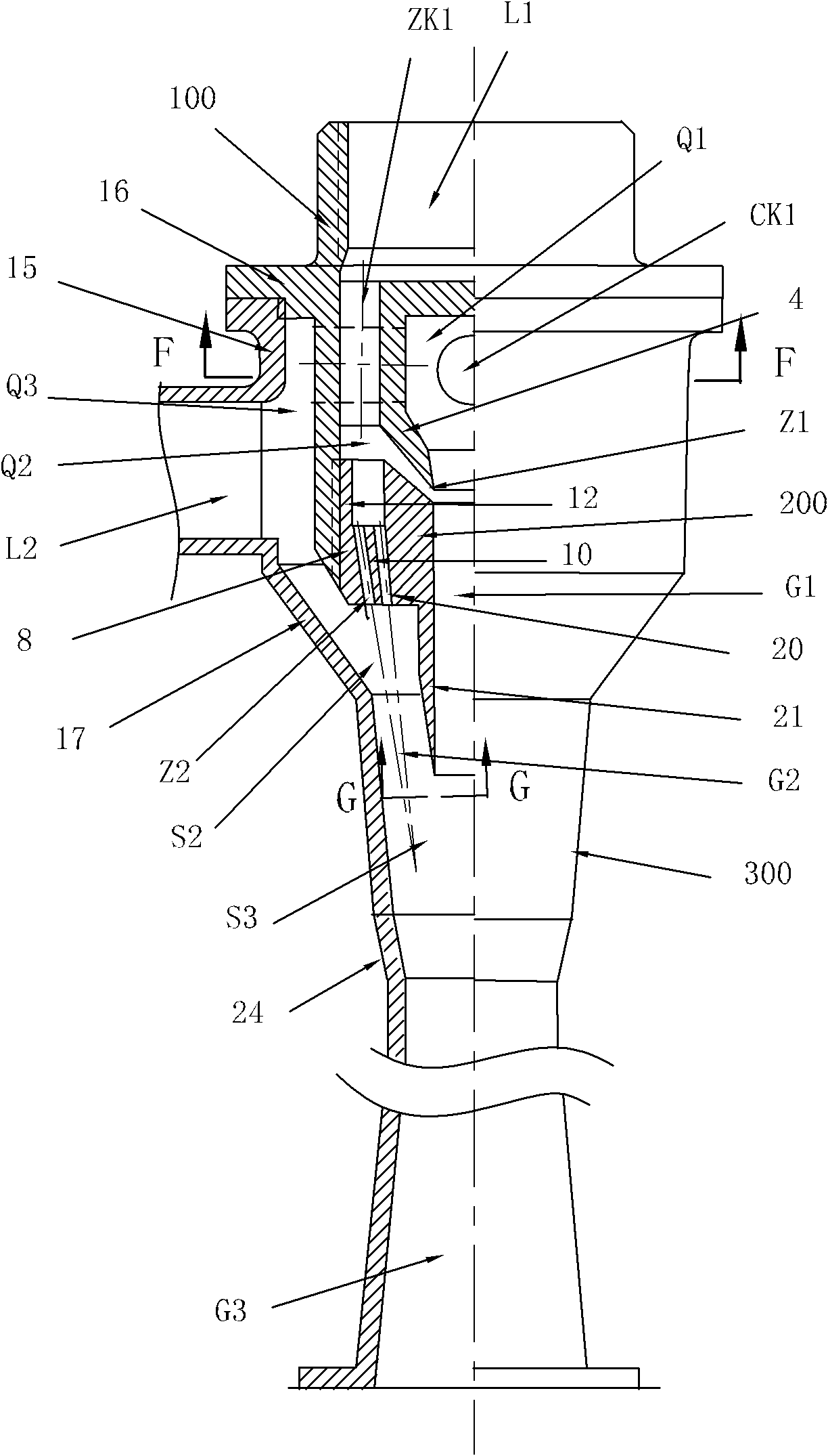
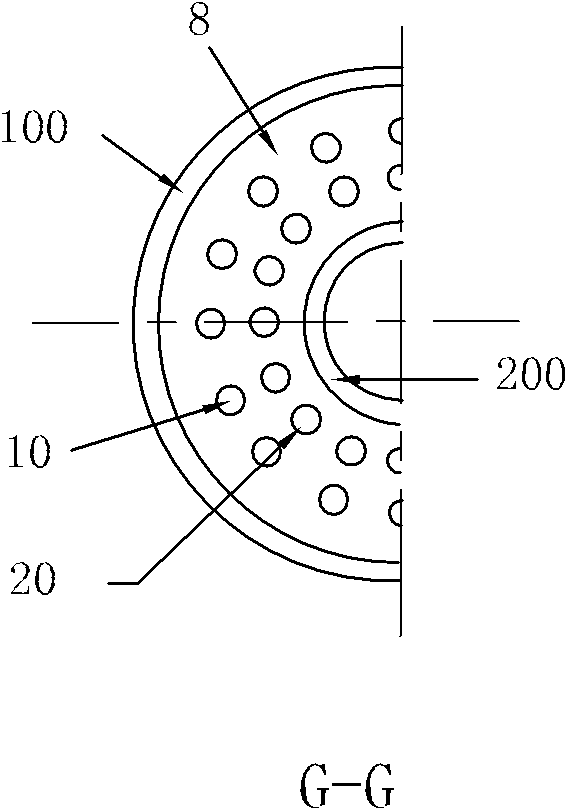
[0042] For the structure of Embodiment 1 of the injection pump of the present invention, see figure 1 and figure 2 . The injection pump is composed of a coaxial distribution assembly 100, an inner tube assembly 200 and an outer casing assembly 300, the distribution assembly 100 and the inner tube assembly 200 are connected in series, and the outer casing assembly 300 is installed on the flow distribution assembly 100 and the inner tube assembly 200 outside. The main fluid inlet pipe L1 is arranged in the center of the top of the flow distribution assembly 100, and the secondary fluid inlet pipe L2 and the general mixing outlet pipe G3 are arranged on the jacket assembly 300 .

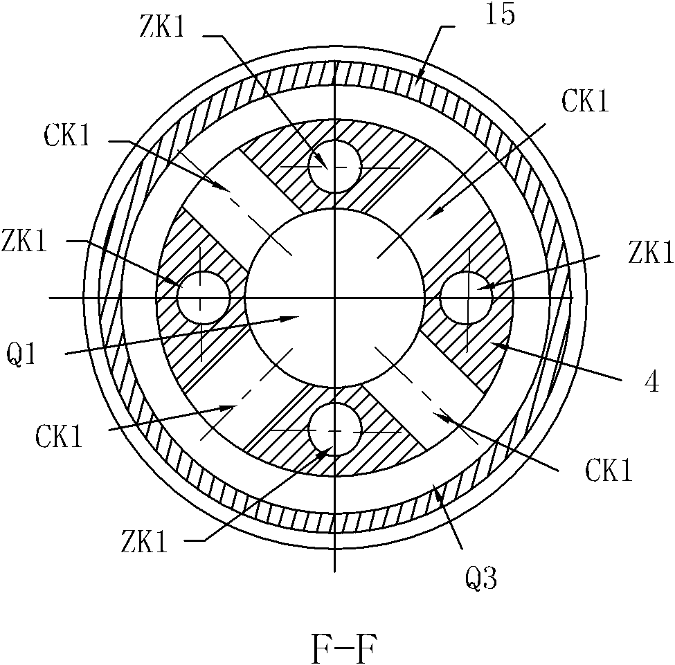
[0043] A flow distribution sleeve 4 is arranged in the middle of the flow distribution assembly 100, and the diameter of the front part of the blind top central cavity Q1' in the center of the flow distribution sleeve 4 is larger than the outlet diameter of the rear part. A plurality of secondary fl...

Embodiment 2

[0049] For the structure of Embodiment 2 of the injection pump of the present invention, see Figure 4 . This embodiment is a two-stage series injection pump, which consists of a coaxial flow distribution assembly 100', an inner tube assembly 200', an outer casing assembly 300' and a second-stage injection assembly 400'. The flow distribution assembly 100' and the inner pipe assembly 200' are connected in series, and the outer casing assembly 300' is set outside the flow distribution assembly 100' and the inner pipe assembly 200'; the second-stage injection assembly 400' is set behind the outer casing assembly 300' outside the department.

[0050] The main fluid inlet pipe L1' is arranged in the center of the top of the flow distribution assembly 100', and the flow distribution sleeve 4' with the blind top center cavity Q1' is set in the middle; multiple secondary ports connected to the blind top center cavity Q1' are evenly distributed horizontally on the peripheral wall of ...

Embodiment 3

[0064] Embodiment 3 of the injection pump of the present invention is an improvement on the first two embodiments. The similarities between this embodiment and the first two embodiments will not be described in detail. The differences after the improvement are:

[0065] The flow channel of the annular mixing tube is very short, and has an inverted cone annular median surface, and the axes of the circular holes constituting the outer ring nozzle are arranged obliquely along the inverted cone annular surface in the center of the annular mixing tube flow channel and the center line of the ejector pump, forming Figure 7 Outer ring swirl nozzle hole 47-3' shown in the left half. The inner ring nozzle has Figure 8 The discontinuous annular tapered slit of uniformly distributed equal-width chute 311' structure shown in the middle and upper part. The direction of the swirling flow generated by the outer ring nozzle and the inner ring nozzle is opposite, and it is easy to maintain i...


PUM


Abstract

The invention provides a jet pump, and relates to a mixed flow jet apparatus. The jet pump is composed of a current distributing assembly, an inner pipe assembly and an outer sleeve assembly which have a same shaft core, wherein the current distributing assembly and the inner pipe assembly are fixedly connected in series, thereby forming a blind top centre cavity and a centre mixing tube; the outer sleeve assembly is sleeved outside the current distributing assembly and the inner pipe assembly, thereby forming an annular mixing chamber, an annular mixing pipe, a total mixing chamber and a total mixing output pipe; an internal ring nozzle and an external ring nozzle are arranged between the current distributing assembly and the inner pipe assembly, a mainstream body sprayed by the internal ring nozzle carries out jet-suction on a secondary fluid of the blind top centre cavity so as to spray to the centre mixing tube, and the secondary fluid is mixed in the centre mixing tube so as to output a centre mixed flow; a mainstream body sprayed by the external ring nozzle carries out jet-suction on a secondary fluid of the blind top centre cavity so as to spray to the annular mixing pipe, and the secondary fluid is mixed in the annular mixing pipe so as to output an annular mixed flow; and the two mixed flows are mutually injected to enter the total mixing chamber and the total mixing output pipe so as to further output in an isotrope voltage-sharing manner. The jet pump provided by the invention has the advantages of smaller weight and axial direction size, high injection rate, great suction force and good property in large flow.

Description

technical field [0001] The invention relates to a mixed flow injection device, in particular to a jet pump used for mixed fluid injection. Background technique [0002] Ejector pump, also known as injector, jet pump, jet pump, is a device that injects low-pressure (or suction pressureless) secondary fluid with relatively high-pressure primary fluid, and completes the primary fluid pumping of secondary fluid. Since the injector has no moving parts, it is reliable and widely used in fluid equipment in various fields. [0003] The existing injector is composed of a set of main fluid inlet pipe, main fluid nozzle, secondary fluid inlet pipe, mixing chamber, mixing pipe or mixing diffuser; the secondary fluid passing into the mixing chamber is sucked by the main fluid jet ejected from the nozzle Into the mixing tube, mixed in the mixing diffuser to equalize the output. The mixing tube of such injectors is generally a single elongated circular tube, such as a typical Venturi tub...

Claims


Application Information

Patent Timeline
Patent Type & Authority Applications(China)
IPC IPC(8): F04F5/00
Inventor 韩铁夫
Owner 韩铁夫
Why Eureka
Try Eureka