Temperature compensation current reference circuit applied to integrated circuit

A technology of temperature compensation and current reference, applied in the direction of adjusting electrical variables, control/regulation systems, instruments, etc., can solve problems such as small resistance value, increased cost of integrated circuits, and difficulty in controlling absolute value

Inactive Publication Date: 2012-09-05
WUXI SI POWER MICRO ELECTRONICS
View PDF5 Cites 12 Cited by
  • Summary
  • Abstract
  • Description
  • Claims
  • Application Information

AI Technical Summary

Problems solved by technology

However, in the current integrated circuit manufacturing process, the resistor with a low temperature coefficient has a very small resistance value per unit area. In order to obtain a microampere-level reference current inside the chip, a large amount of integrated circuit area is required to manufacture the resistor, which will also increase integration. circuit cost
Moreover, the low temperature coefficient resistor is manufactured by diffusion process, and its absolute value is difficult to control

Method used


Image

  • Temperature compensation current reference circuit applied to integrated circuit
  • Temperature compensation current reference circuit applied to integrated circuit
  • Temperature compensation current reference circuit applied to integrated circuit

Examples


Embodiment Construction

[0018] The present invention will be further described below in conjunction with drawings and embodiments.

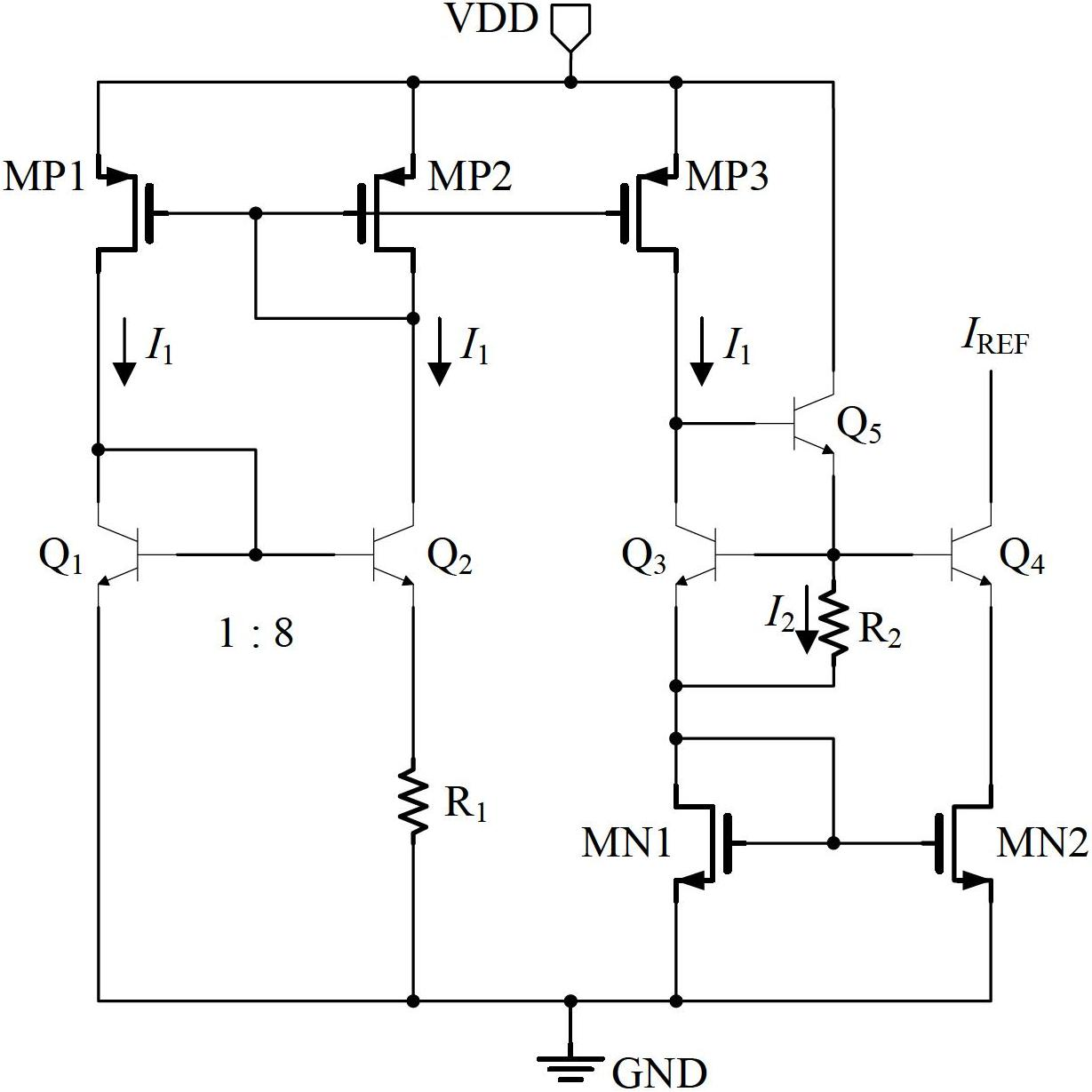
[0019] The temperature compensation current reference circuit designed by the present invention is as figure 2 As shown, I REF is the temperature-compensated reference current generated by the present invention. MP1, MP2, and MP3 are mutually matching current mirrors, the current mirror ratio is 1:1:1, and its type can be PMOS transistors or PNP transistors; transistors Q1 and Q2 are mutually matching NPN transistors, and the emitter of Q2 The area is 8 times that of Q1; resistor R1 adopts a high-value polycrystalline resistor with a temperature coefficient of -2341ppm / ℃; transistors Q3 and Q4 match each other, and the emitter area ratio is 1:1; MN1 and MN2 are current mirrors that match each other. The ratio of current mirror is 1:1, and its type can be NMOS transistor or NPN triode; resistor R2 adopts P-type ion implantation resistor with temperature coefficient of...


PUM


Abstract

The invention provides a temperature compensation current reference circuit applied to an integrated circuit, wherein a sixth transistor, a seventh transistor and an eighth transistor are mutually matched current mirrors, and the proportion of the current mirrors is 1:1:1; a ninth transistor and a tenth transistor are mutually matched current mirrors, the proportion of the current mirrors is 1:1; a first transistor and a second transistor are mutually matched NPN triodes; a third transistor and a fourth transistor are mutually matched; and a first resistor utilizes a high-value polycrystal resistor, and a second resistor utilizes a P-type ion injection resistor. Positive temperature coefficient current and negative temperature coefficient current are added to obtain temperature compensation reference current, and then the temperature compensation reference current is provided for other circuits by utilizing the current mirrors. The temperature compensation current reference circuit applied to the integrated circuit, disclosed by the invention, has the advantages that the reference current changes very tiny in a certain temperature change range (minus 40-130 DEG C).

Description

technical field [0001] The invention relates to a current reference circuit of an integrated circuit, in particular to a temperature compensation current reference circuit applied to an integrated circuit. Background technique [0002] It is often difficult to generate a temperature-independent reference current in an integrated circuit, because in the integrated circuit manufacturing process, resistors are usually manufactured by diffusion or ion implantation, and this resistor has a specific temperature coefficient. , which means that the resistance value will change as the operating temperature of the IC changes. The temperature dependence of the resistance value causes the reference current value to vary with temperature. [0003] In order to overcome the above-mentioned problem that the reference current varies with temperature, an external resistor R11 and a bandgap voltage reference Bandgap can be used to form a temperature-independent current source, such as figure...

Claims


Application Information

Patent Timeline
Patent Type & Authority Applications(China)
IPC IPC(8): G05F3/26
Inventor 谭在超朱勤为
Owner WUXI SI POWER MICRO ELECTRONICS
Why Eureka
Try Eureka