Vibration detection device, air pressure detection terminal, and acceleration detection system

A technology of vibration detection and air pressure detection, which is applied in the direction of measuring acceleration, speed/acceleration/shock measurement, measuring devices, etc.

Inactive Publication Date: 2012-09-05
SANYO ELECTRIC CO LTD
View PDF6 Cites 10 Cited by
  • Summary
  • Abstract
  • Description
  • Claims
  • Application Information

AI Technical Summary

Problems solved by technology

However, when a battery is used to supply power to the vibration de

Method used


Image

  • Vibration detection device, air pressure detection terminal, and acceleration detection system
  • Vibration detection device, air pressure detection terminal, and acceleration detection system
  • Vibration detection device, air pressure detection terminal, and acceleration detection system

Examples


no. 1 Embodiment approach

[0032] refer to Figure 1 ~ Figure 4 The configuration of the vibration detection system 1 according to the first embodiment of the present invention will be described.

[0033]

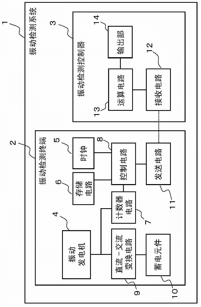
[0034] figure 1 It is a block diagram for explaining the configuration of the vibration detection system 1 .

[0035] The vibration detection system 1 is composed of a vibration detection terminal 2 and a vibration detection controller 3 . The vibration detection terminal 2 includes a vibration generator 4 , a clock 5 , a storage circuit 6 , a counter circuit 7 , a control circuit 8 , a DC-AC conversion circuit 9 , an electric storage element 10 , and a transmission circuit 11 . The vibration detection controller 3 includes a receiving circuit 12 , an arithmetic circuit 13 , and an output unit 14 .

[0036] The vibration detection system 1 measures the vibration frequency of the vibration generator 4 and the time required for the vibration in the vibration detection terminal 2 . In addition, in...

Embodiment 1

[0066] refer to Figure 5 The calculation method of the acceleration related to the first embodiment of the vibration detection system 1 will be described. Figure 5 (a) and Figure 5 (b) is a flowchart showing the calculation method of the acceleration related to the first embodiment. Figure 5 (a) is the processing in the vibration detection terminal 2, Figure 5 (b) is processing in the vibration detection controller 3 . In addition, in Embodiment 1, the control circuit 8 is based on Figure 4 No.1 of the operation table shown is controlled.

[0067] refer to Figure 5 (a), in vibration detection terminal 2, if vibration generator 4 vibrates (S1), then control circuit 8 adopts the clock signal that obtains from clock 5, by the vibration of vibration generator 4 in the fixed time by counter circuit 7 The number is counted (S2). Here, the fixed time can be freely set by the user, for example, it is set to 1 second. Next, the control circuit 8 judges whether or not the...

Embodiment 2

[0070] Next, refer to Figure 6 The calculation method of the acceleration related to the second embodiment of the vibration detection system 1 will be described. Figure 6 It is a flowchart showing the calculation method of the acceleration in the second embodiment. Figure 6 The processing shown in the flowchart of is performed in the vibration detection terminal 2 . In addition, in Embodiment 2, the control circuit 8 is based on Figure 4 Control No.2 of the operation table shown.

[0071] In vibration detection terminal 2, if vibration generator 4 vibrates (S11), then control circuit 8 adopts the clock signal that obtains from clock 5, counts the vibration number of vibration generator 4 in fixed time by calculator 7 ( S12). Here, the fixed time can be freely set by the user, for example, it is set to 60 seconds. The control circuit 8 creates data for acceleration calculation which associates the counted number of vibrations of the vibration generator 4 with a fixed t...


PUM


Abstract

Provided is a vibration detection device wherein it is possible to store the power generated by the device itself and to reduce the size of the device. Also provided are an acceleration detection system and an air pressure detection terminal using said vibration detection device. A vibration detection terminal (2) is provided with a vibration power generator (4) which generates AC voltage by vibrating, a DC-AC conversion circuit (9) which converts the AC voltage generated by means of the vibration power generator (4) into DC voltage, a power storage element (10) which stores power by means of the converted DC voltage, and a counter circuit (7) which counts the number of vibrations of the AC voltage generated by means of the vibration power generator (4). The number of vibrations counted by means of the counter circuit (7) during a predetermined time period is sent to a vibration detection controller (3) as acceleration calculating data. The power storage element (10) supplies power to each constitutional element of the vibration detection terminal (2).

Description

technical field [0001] The present invention relates to a vibration detection device using a vibration device that generates an AC voltage by vibrating, an air pressure detection terminal and an acceleration detection system using the vibration detection device. Background technique [0002] When buildings such as bridges and buildings, or equipment in factories become obsolete, there is a possibility that serious accidents such as collapse may develop. Therefore, conventionally, measures have been taken to prevent accidents by installing vibration detection devices in buildings and the like to detect and manage vibrations in buildings and the like. However, when a battery is used to supply power to the vibration detection device, the battery needs to be replaced periodically. Therefore, there has been proposed a vibration detection device that does not require battery replacement by combining a vibration sensor and a generator (for example, Patent Document 1). [0003] pr...

Claims


Application Information

Patent Timeline
IPC IPC(8): G01V1/18G01H1/00G01H11/06
CPCG01H11/06G01L9/0008G01P15/00G01P15/125
Inventor 泉诚松原直辉
Owner SANYO ELECTRIC CO LTD
Why Eureka
Try Eureka