Turning method for winding heat-proof layer on metal shell cabin section and device thereof

A technology of metal shell and heat-proof layer, which is applied in the field of non-metallic material cutting and processing, can solve the problems of slag falling, deblocking, outer circle deformation, etc., and achieve easy layering, easy alignment, and reduction of clamping deformation Effect

Active Publication Date: 2012-09-12
HUBEI SANJIANG AEROSPACE GRP HONGYANG ELECTROMECHANICAL
View PDF4 Cites 13 Cited by
  • Summary
  • Abstract
  • Description
  • Claims
  • Application Information

AI Technical Summary

Problems solved by technology

[0006] 1. When turning the heat-resistant layer, because the cutting parameters are not easy to choose, the heat-resistant layer is prone to delamination, cracks, slag falling, deblocking, and fracture, and the qualified rate of finished products is low
[0007] 2. The clamping method of the prior art is to use the three-jaw chuck of the lathe to clamp the parts for processing. The clamped parts are radially stressed, and the parts will produce elastic deformation. The processed parts are outer circles and inner circles. After the part is removed, the elastic deformation of the part recovers, so that the inner hole returns to a circular shape, but the outer circle is deformed, which affects the dimensional accuracy and shape accuracy of the processed part

Method used

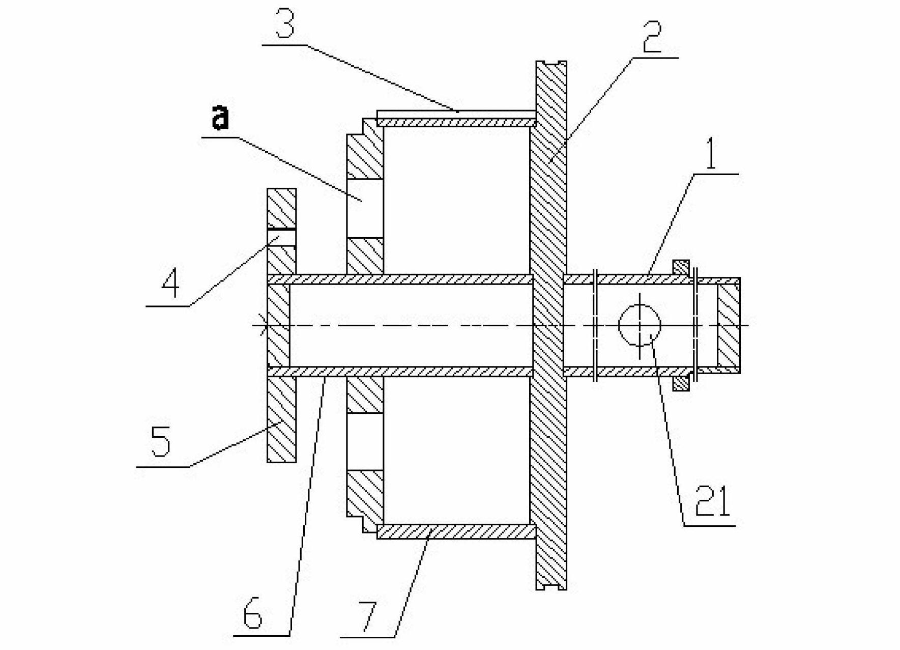
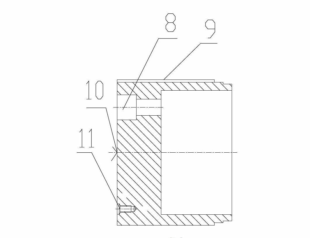
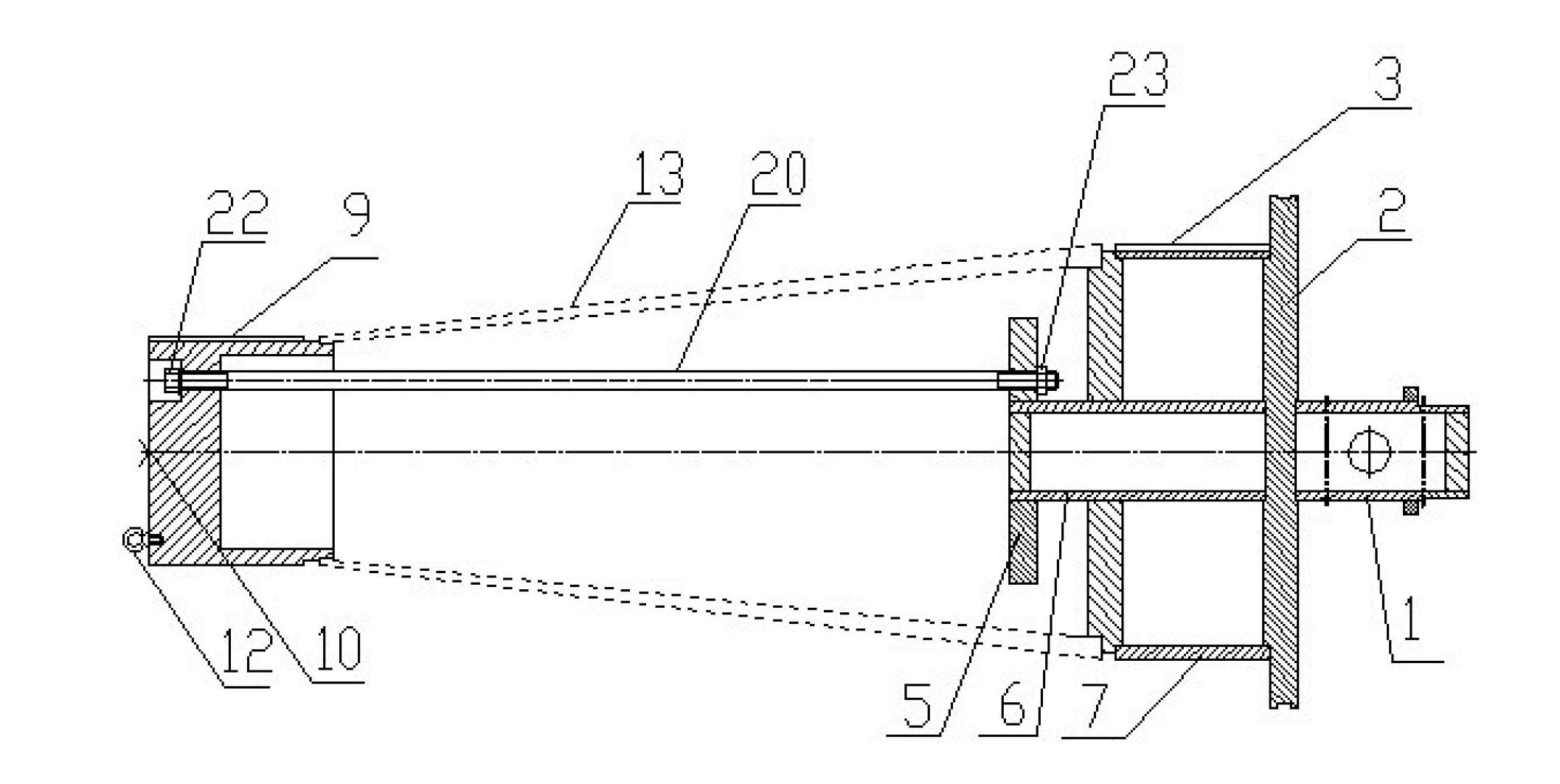

Image

  • Turning method for winding heat-proof layer on metal shell cabin section and device thereof
  • Turning method for winding heat-proof layer on metal shell cabin section and device thereof
  • Turning method for winding heat-proof layer on metal shell cabin section and device thereof

Examples


specific Embodiment 1

[0066] Specific embodiment 1: the spindle speed n=80r / min, the feed rate f=0.2mm, the cutting depth 0.3mm, the gap between the inner hole of the front end of the metal shell cabin and the winding mandrel is 0.2mm, and the metal shell cabin The butt gap between the inner hole at the rear end of the section and the winding mandrel is 0.15mm, the butt gap between the inner hole at the front end of the metal shell cabin section and the axial positioning clamp is 0.1mm, and the butt gap between the inner hole at the rear end of the metal shell cabin section and the axial positioning clamp 0.1mm. A total of 10 heat-resistant layers were processed, all of which were in good condition, and the qualified rate of finished products was 100%.

specific Embodiment 2

[0067] Specific embodiment 2: the speed of the main shaft is n=70r / min, the feed rate is f=0.1mm, the cutting depth is 0.1mm, the gap between the inner hole of the front end of the metal shell cabin and the winding mandrel is 0.25mm, and the metal shell cabin The gap between the inner hole at the rear end of the segment and the winding mandrel is 0.1mm, the gap between the inner hole at the front end of the metal shell cabin and the axial positioning clamp is 0.09mm, the inner hole at the rear end of the metal shell cabin and the axial positioning clamp Butt gap 0.05mm. A total of 10 pieces of heat-resistant layers were processed, of which 1 piece of heat-resistant layer dropped slag, and the qualified rate of finished products was 90%.

specific Embodiment 3

[0068] Specific embodiment 3: the spindle speed is n=60r / min, the feed rate is f=0.1mm, the cutting depth is 0.3mm, the gap between the inner hole of the front end of the metal shell cabin and the winding mandrel is 0.18mm, and the metal shell cabin is The gap between the inner hole at the rear end and the winding mandrel is 0.1mm, the gap between the inner hole at the front end of the metal shell cabin and the axial positioning clamp is 0.15mm, and the inner hole at the rear end of the metal shell cabin is docked with the axial positioning clamp The gap is 0.12mm. A total of 10 heat-resistant layers were processed, all of which were in good condition, and the qualified rate of finished products was 100%.

[0069] Below, 5 groups of cutting parameters of the present invention are not used, and 5 groups of cutting parameters of the present invention are used, each group processes 10 heat-resistant layers, and the comparison list of the processing quality of the heat-resistant l...


PUM


Abstract

The invention relates to the technical field of nonmetal material cutting processing, and discloses a turning method for winding a heat-proof layer on a metal shell cabin section and a winding core mould. In the invention, the parameters of the turning method are controlled, and the phenomena of splitting, cracking, scrap falling, block drop and fracture easily caused by the existing machining turning of the heat-proof layer are effectively improved, thus the qualified rate of finished products is improved; by changing the clamping mode, the clamping deformation of parts in processing is reduced, and the alignment difficulty is reduced; and through the improvement of the manufacturing method of the heat-proof layer, the heat-proof layer can be directly wound on the metal shell cabin section, the manufacturing and assembling processes of the heat-proof layer are simplified, the labor intensity is lowered, and the connection between the heat-proof layer and the metal shell cabin section is tighter. The processing method disclosed by the invention is universal, realizes low rejection rate of the parts, and is safe and reliable to use; and the provided winding core mould has a simple structure and is easy to manufacture and convenient to use.

Description

technical field [0001] The invention relates to the technical field of cutting processing of non-metallic materials. Background technique [0002] Aerospace vehicles, launch vehicles, missiles and other high-tech products will generate a lot of heat during launch and flight, which will affect the normal operation of instruments and meters in these products, make electronic devices invalid, and threaten the successful launch or normal flight of products . For this reason, glass fiber reinforced plastic materials are generally wound on the outer surface of the metal shell of each cabin for heat protection and heat insulation. Each cabin section is a large, thin-walled annular part, with thin wall thickness, poor rigidity, and easy deformation. The thermal conductivity of FRP material is small, limited by the temperature resistance of the matrix resin, the heat is not easily dissipated during processing, the temperature in the cutting area rises rapidly during the cutting pro...

Claims


Application Information

Patent Timeline
Patent Type & Authority Applications(China)
IPC IPC(8): B23P17/00B23B1/00B29C53/82
Inventor 李艳梅任延玲葛光员
Owner HUBEI SANJIANG AEROSPACE GRP HONGYANG ELECTROMECHANICAL
Why Eureka
Try Eureka