High fidelity transistor audio power amplifying device

A technology of amplifying device and audio power, applied in the field of electronics, can solve the problems of lack of mellow feeling and sweetness, less sound detail, poor bass and treble listening feeling, etc., to achieve broad market application prospects, easy production and power utilization high rate effect

Inactive Publication Date: 2012-09-12
侯德亮 +1
View PDF6 Cites 6 Cited by
  • Summary
  • Abstract
  • Description
  • Claims
  • Application Information

AI Technical Summary

Problems solved by technology

[0004] 1. Class A audio power amplifiers have high heat generation, low efficiency, generally small output power, high cost, poor stability and safety, and only a few power amplifiers use this circuit
[0005] 2. The crossover distortion (crossover distortion) of the signal amplified by the Class B audio power amplifier device is very large, and the details of the sound cannot be expressed. Generally, the power amplifier does not use this circuit form
[0010] 1. Due to the small size and concentrated and dense components, this determines the size of the audio signal and the interference between the signals is large, and it is easy to self-excite
[0011] 2. All components work at high temperature, and the amplification performance becomes poor
[0012] 3. The circuit is fixed and difficult to modify
[0013] 4. The output power is generally small and cannot meet the requirements in most cases
[0014] 5. The sound effect also has some common shortcomings of transistor power amplifiers
[0016] 1. Large volume, high power consumption and low efficiency
[0017] 2. High cost and short life
[0018] 3. High maintenance cost
[0019] 4. Small output power
[0020] 5. The existence of the output transformer determines that the bass and treble have large distortion, poor linearity and poor sense of hearing
[0021] At present, the common disadvantages of the sound quality of the power amplifiers produced by the above existing audio power amplifiers are: the sound is relatively digital; the sound is thin, lacking in mellowness and sweetness; There is a strong glitch feeling, which is unbearable for a long time and at high volume; the three-dimensional effect of the space is poor; the efficiency and sound quality cannot be balanced; the crossover distortion of Class A and B and Class B is large, the sound details are few, and even the details are completely submerged; transient Large intermodulation distortion, poor sound clarity and layering, and small dynamic range
However, the tube power amplifier has large volume, high power consumption, low efficiency, high cost, short life, high maintenance cost, low output power, and poor bass and treble hearing.
[0022] With the improvement of people's material and cultural level, the sound quality requirements for audio equipment are getting higher and higher. The existing audio power amplifiers are far from being able to meet more music lovers and audiophiles with fanatical and demanding sound quality requirements. The needs of audiophiles are increasing, and audio power amplifiers with complex circuits and high prices cannot be accepted by the working-class people. Therefore, there is an urgent need in the market for a low-cost, easy-to-manufacture, free-adjustment, safe and efficient, and beautiful sound quality. and other advantages, and a simple structure of high-fidelity audio power amplifier

Method used


Image

  • High fidelity transistor audio power amplifying device
  • High fidelity transistor audio power amplifying device
  • High fidelity transistor audio power amplifying device

Examples


Embodiment Construction

[0083] In order to make the object, technical solution and advantages of the present invention clearer, the present invention will be further described in detail below with reference to the accompanying drawings and examples.

[0084] The key of the present invention is to convert the input audio signal into an audio differential mode signal. The audio differential mode signal refers to the composite signal of the audio signal of the sources of the two field effect tubes in the field effect tubes connected by two sources, and then It is converted into a normal audio signal, so that the entire amplifying device forms a real circuit push-pull working state, thereby obtaining an audio signal with beautiful sound quality.

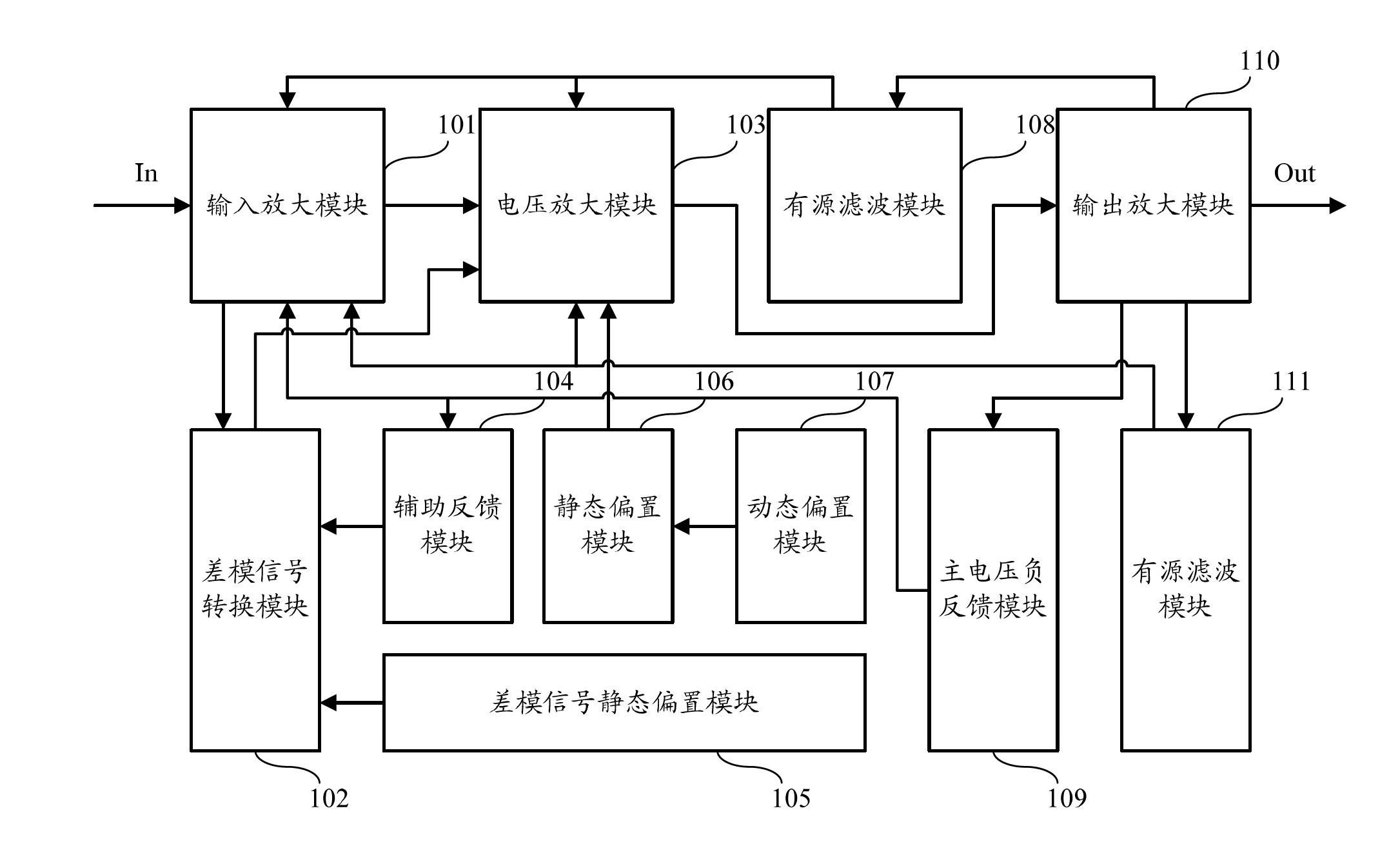
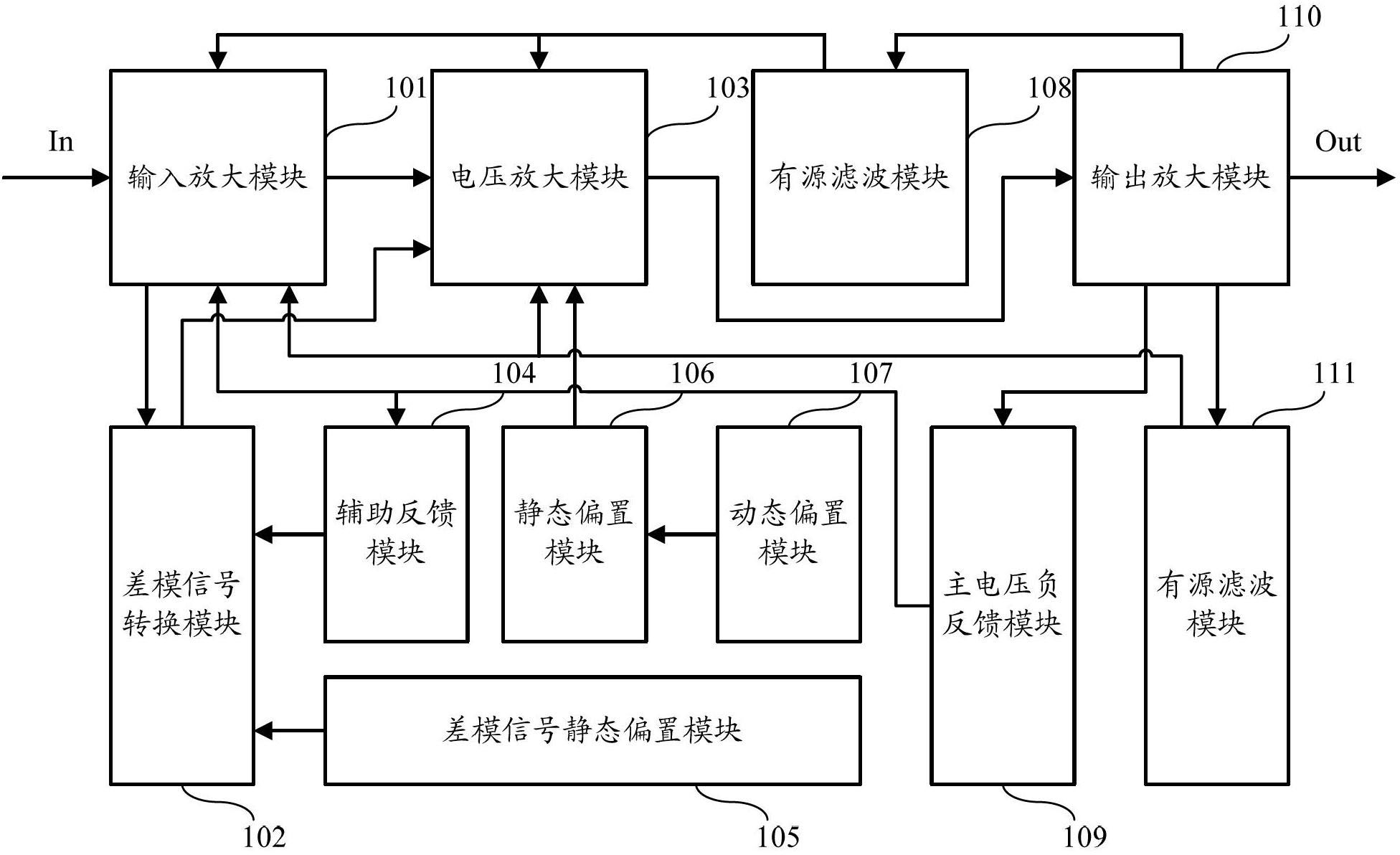
[0085] figure 1 It is a schematic structural diagram of a high-fidelity transistor audio power amplification device according to an embodiment of the present invention, as figure 1 As shown, the device includes:

[0086] The input amplification module 101 is ...


PUM


Abstract

The invention discloses a high fidelity transistor audio power amplifying device comprising an input amplifying module, a difference module signal converting module, a voltage amplifying module, a main voltage negative feedback module, an auxiliary feedback module and a difference module signal offsetting module, wherein the input amplifying module is used for increasing the input resistance, amplifying an input audio signal and generating an audio difference module signal; the difference module signal converting module is used for converting, amplifying and outputting the audio difference module signal; the voltage amplifying module is used for performing voltage amplification on the audio signal amplified by the input amplifying module and the difference module signal converting module; the main voltage negative feedback module is used for feeding back the audio signal to the input amplifying module; the auxiliary feedback module is used for feeding back the audio signal to the difference module signal converting module; and the difference module signal offsetting module is used for providing static offset current for the difference module signal converting module. The device has the advantages of simple structure, low cost, easiness in manufacture, non-debugging operation, good safety and efficiency, and beautiful tone quality, etc.

Description

technical field [0001] The invention relates to the field of electronic technology, in particular to a high-fidelity transistor audio power amplifying device. Background technique [0002] At present, known audio power amplifiers are used in power amplifiers, and are generally divided into two categories, transistors and electronic tubes, according to the materials used. According to the structure, there are two kinds of discrete components and integrated circuits; according to the circuit working mode, there are two kinds of analog and digital. No matter what type of audio power amplification device, there are some inherent problems and defects that are difficult to solve. The circuit performance has its own advantages and disadvantages, which leads to the cost, reliability, efficiency and sound quality of the power amplifier made by the audio power amplification device. Can't be satisfying at the same time. [0003] Among them, in the discrete component transistor analog...

Claims


Application Information

Patent Timeline
Patent Type & Authority Applications(China)
IPC IPC(8): H03F3/20H03F1/32
Inventor 侯德亮田明
Owner 侯德亮
Why Eureka
Try Eureka