Cutter with function of decoupling temperature of turning area

A cutting tool and functional technology, applied in the field of cutting tools with temperature decoupling function in the turning area, can solve the problems of high difficulty in arranging galvanic couples, large measurement range, short response time, etc., and achieve high reliability of operation and measurement results, and anti-interference The effect of strong ability and simple structure

Inactive Publication Date: 2012-09-19
HUAZHONG UNIV OF SCI & TECH
View PDF6 Cites 11 Cited by
  • Summary
  • Abstract
  • Description
  • Claims
  • Application Information

AI Technical Summary

Problems solved by technology

These methods have their own advantages and disadvantages. The galvanic couple method is direct, simple, and reliable in data, but it has the problems of high difficulty in arranging the galvanic couple and poor measurement dynamic response. Infrared and other non-contact test methods have short response time and large measurement range but have environmental requirements. Higher, difficult to select the measurement position and poor accuracy
In addition, summarizing the above test methods, the common disadvantage is that the cutting temperature of the test is the average temperature, and the decoupling test of the temperature in the turning area cannot be performed.

Method used


Image

  • Cutter with function of decoupling temperature of turning area
  • Cutter with function of decoupling temperature of turning area
  • Cutter with function of decoupling temperature of turning area

Examples


Embodiment Construction

[0014] In order to make the object, technical solution and advantages of the present invention clearer, the present invention will be further described in detail below in conjunction with the accompanying drawings and embodiments. It should be understood that the specific embodiments described here are only used to explain the present invention, not to limit the present invention.

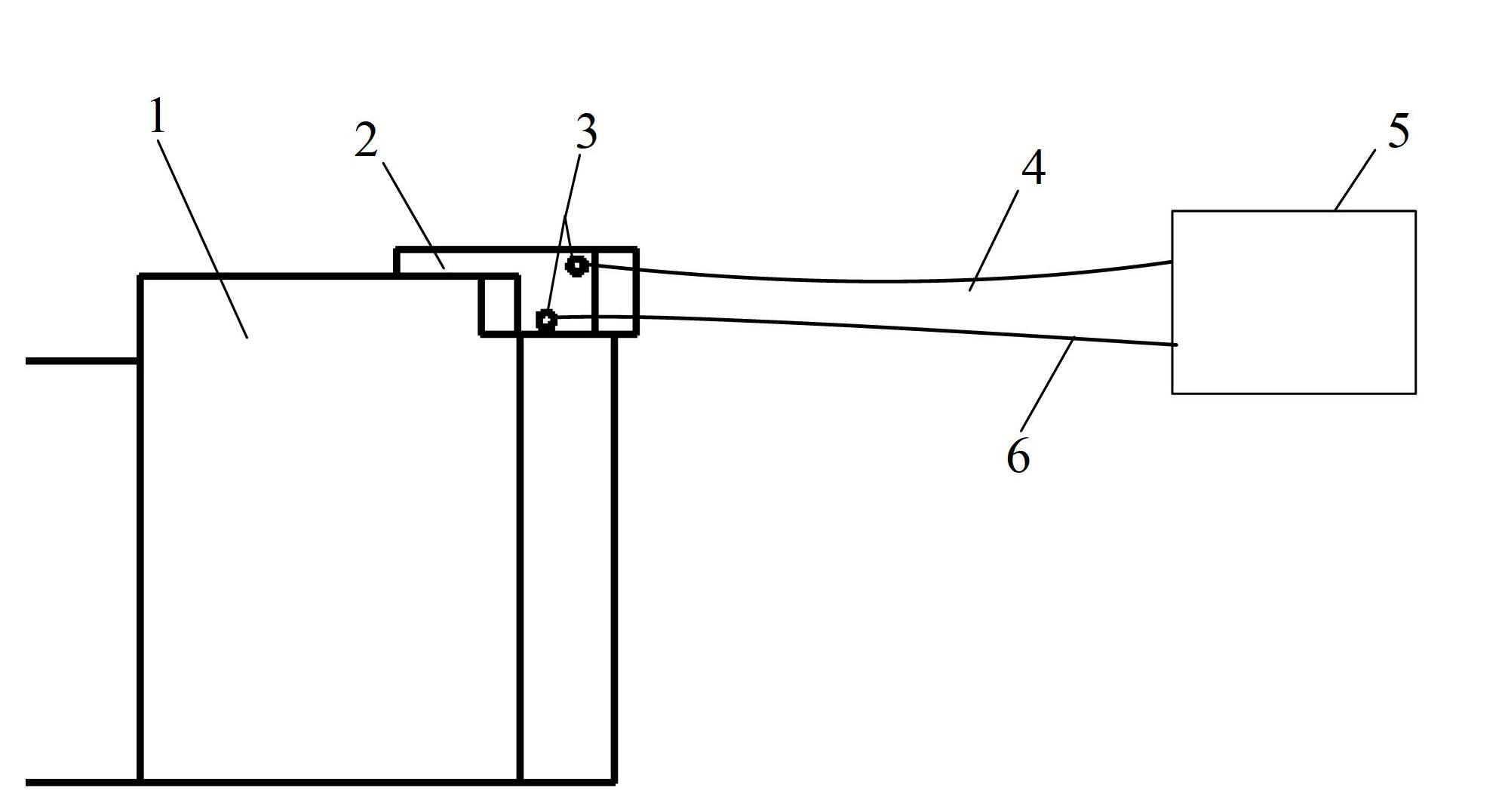
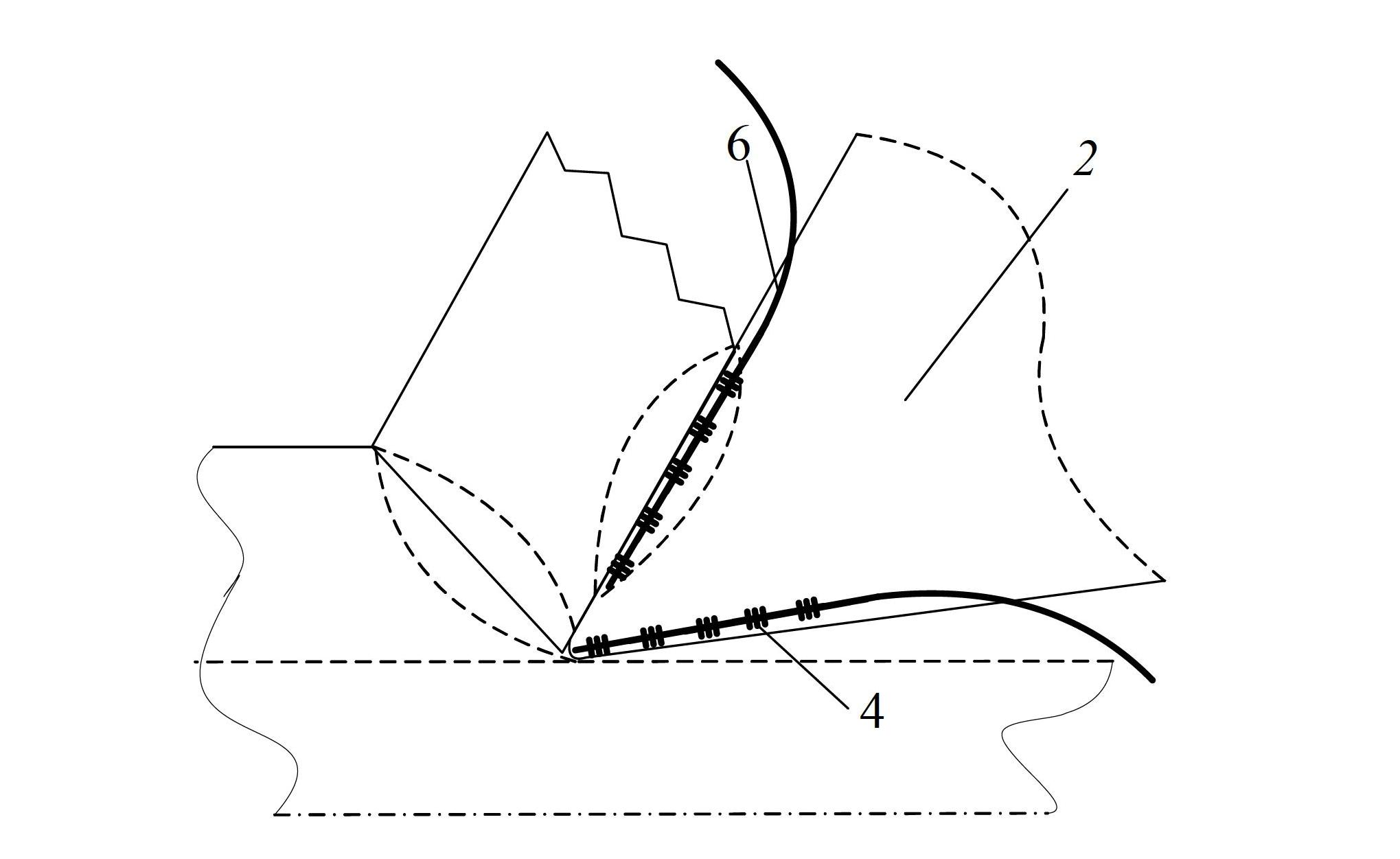
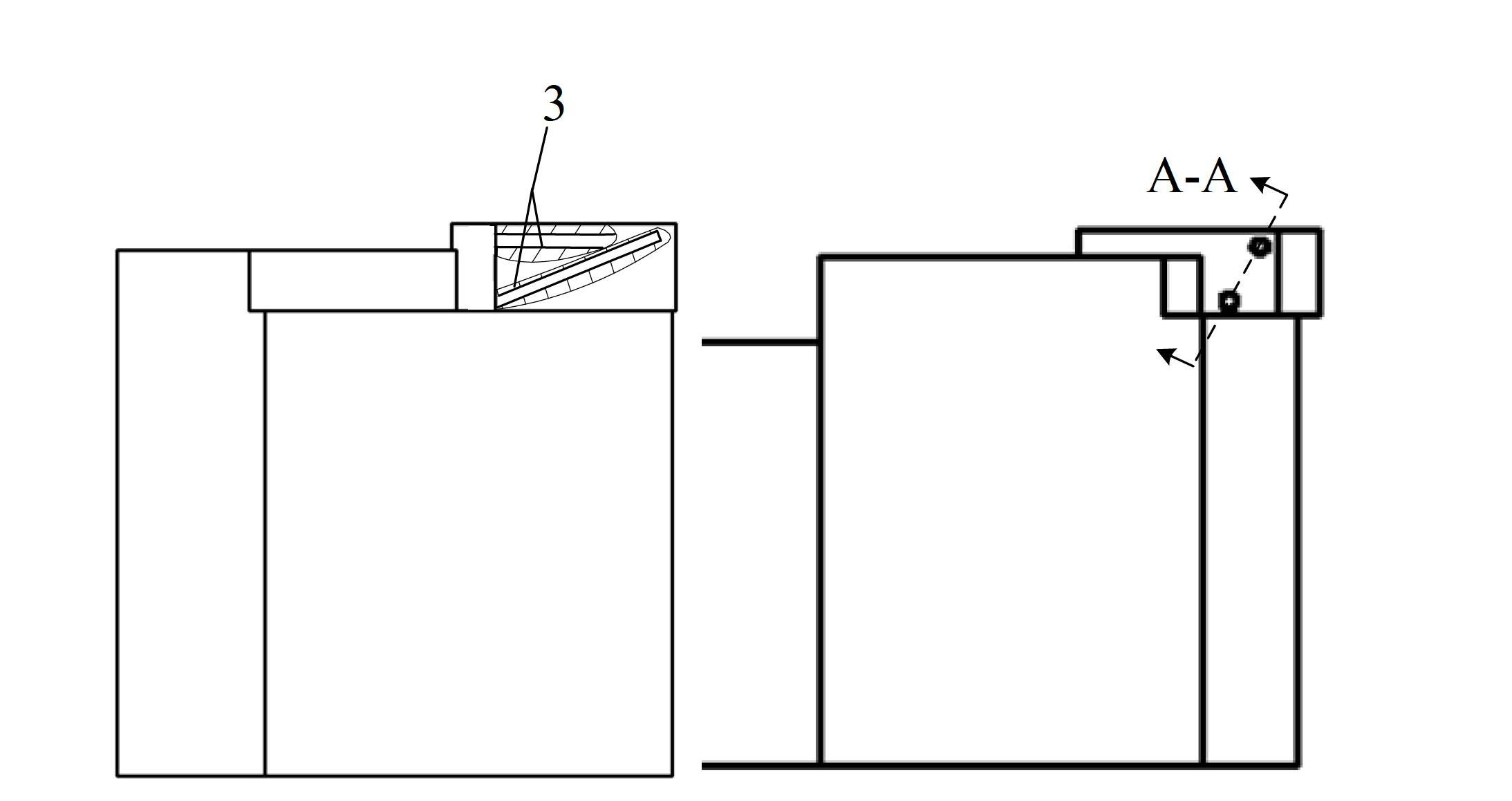
[0015] Such as figure 1 As shown, the turning tool bar 1 is equipped with a machine clamp blade 2 for turning, and a micro blind hole 3 is opened on the machine clamp blade for turning. The first and second high-temperature optical fiber gratings 4 and 6 respectively test the first and second heat source areas. For the temperature distribution, the high-temperature fiber grating 4 tests the heat generated by the first heat source (shear band heat source), and the high-temperature fiber Bragg grating 6 tests the second heat source (the heat source on the chip contact surface). Generally speaking, t...


PUM


Abstract

The invention discloses a cutter with a function of decoupling the temperature of a turning area. The cutter comprises a turning cutter bar and a blade arranged on the turning cutter bar, wherein two test micro blind holes are formed in the blade and used for accommodating high temperature fiber gratings; one blind hole is positioned under the front surface of the cutter; the other blind hole is positioned in the blade, and the bottom of the blind hole tightly leans against a cutter point; the axis of one blind hole is perpendicular to a cutting edge, the distance between the bottom of the blind hole and the cutting edge is 0.2 to 0.8mm, the distance between the blind hole and the front surface is 0.5 to 1.2mm, and the blind hole deviates from the cutter point by 1 to 1.5mm and is used for testing the temperature distribution of a cutter scrap contact surface; and the distance between the other blind hole and the external surface of the cutter point is 0.2 to 0.5mm, an included angle between the axis of the blind hole and the front surface is 20 to 30 degrees, and the blind hole points to the inside of the blade. The cutter can realize multi-point measurement in the turning micro area, is high in dynamic property, micro area test property, dynamic temperature display property and test accuracy, and can well decouple heat generated in a cutting micro area.

Description

technical field [0001] The invention belongs to the precision machining technology, and in particular relates to a cutting tool with a temperature decoupling function in a turning area. The cutting tool uses a high-temperature optical fiber grating to realize multi-point testing in the micro-area of ​​the turning area. Background technique [0002] There are two main heat source areas in the turning process, namely the first heat source and the second heat source, also known as the shear band heat source and the chip contact heat source. According to theoretical analysis, the first heat source has little influence on the temperature distribution of the tool rake face, but has a greater influence on the position of the tool tip. The second heat source has a greater impact on the chip contact surface, but less on other areas of the tool. Therefore, if the first and second heat sources can be tested in real time and accurately, it will have a great impact on the design of key p...

Claims


Application Information

Patent Timeline
Patent Type & Authority Applications(China)
IPC IPC(8): B23B27/00B23Q17/24B23Q17/09
Inventor 杨文玉闫琳金宏平
Owner HUAZHONG UNIV OF SCI & TECH
Why Eureka
Try Eureka