Control circuit of elevator brake

A technology of elevator brakes and control circuits, applied in elevators, hoisting devices, transportation and packaging, etc., can solve the problems of only one type of brakes, increasing the difficulty of design, manufacture and maintenance, etc.

Inactive Publication Date: 2012-09-19
KINETEK DE SHENG SHUNDE MOTOR CO LTD
View PDF10 Cites 10 Cited by
  • Summary
  • Abstract
  • Description
  • Claims
  • Application Information

AI Technical Summary

Problems solved by technology

The brake is a safety component of the elevator, so the braking speed of the brake must meet the emergency stop of the elevator. At the same time, the brake is a component of the elevator, and the braking noise cannot affect the normal life of the user. In the existing brake control circuit, the brake There is only one kind of braking speed and braking noise, and the two are contradictory. The faster the braking speed, the greater the noise, and the slower the braking speed, the smaller the noise. To solve the above problems, the designed brake can only be While the braking speed meets the safety requirements, the noise is reduced as much as possible, but such a brake increases the difficulty of design, manufacture and maintenance

Method used


Image

  • Control circuit of elevator brake
  • Control circuit of elevator brake
  • Control circuit of elevator brake

Examples


Embodiment 1

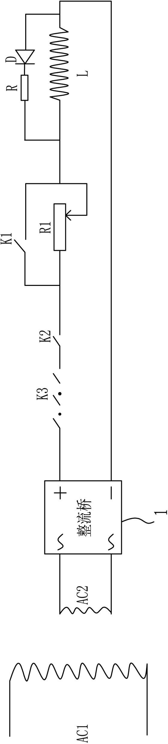
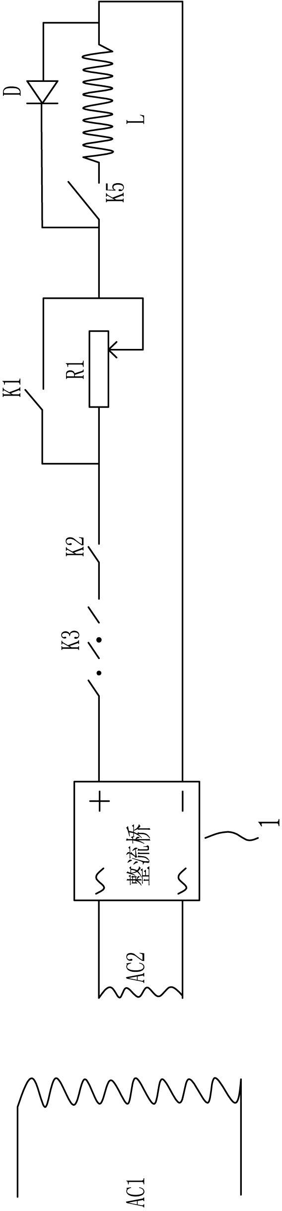
[0016] Embodiment 1, combining image 3 , a control circuit for an elevator brake, including a transformer, a safety switch K3, a brake switch K2, an economic variable resistor R1, an emergency stop switch K5 and a brake coil L, and the transformer includes a primary winding AC1 and a secondary winding AC2, the secondary The two output ends of the winding are respectively connected to the rectifier circuit 1, the safety switch K3, the brake switch K2, the economic variable resistor R1, the emergency stop switch K5 and the brake coil L are connected in series between the positive pole and the negative pole of the rectifier circuit 1, and the brake coil L A reverse diode D is connected in parallel between the input terminal and output terminal of the reverse diode D, and the output terminal of the reverse diode D faces the anode of the rectifier circuit 1, and the emergency stop switch K5 is set at the input terminal of the brake coil L. The emergency stop switch K5 and the reve...

Embodiment 2

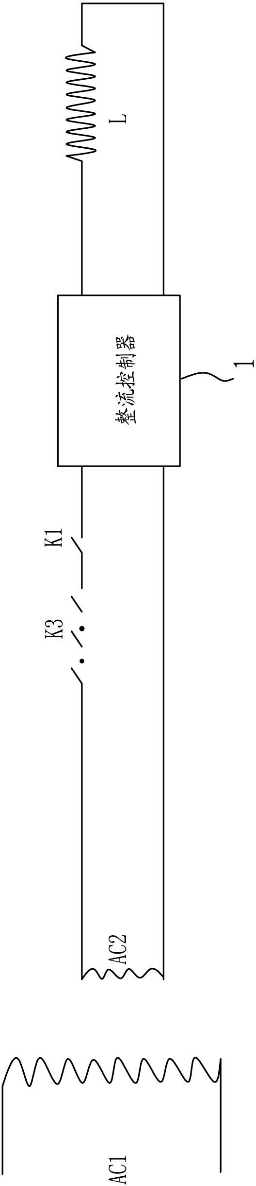
[0017] Example 2, combined with Figure 4 , a control circuit for an elevator brake, including a transformer, a safety switch K3, a brake switch K2, an emergency stop switch K5 and a brake coil L, the transformer includes a primary winding AC1 and a secondary winding AC2, and the two output ends of the secondary winding AC2 The rectifier controller 1 is connected in series between them, the safety switch K3 and the brake switch K2 are connected in series between the two output terminals of the secondary winding AC2, the brake coil L and the emergency stop switch K5 are connected in series between the positive pole and the negative pole of the rectifier controller 1. The rectification controller (which is the prior art) includes a rectification circuit, a step-down circuit and a voltage stabilization circuit. When the elevator is in the normal standby state, the emergency stop switch K5 and the safety switch K3 are both closed. When the elevator receives a running command, the ...


PUM


Abstract

The invention relates to a control circuit of a fast and low-noise brake and belongs to the technical field of an elevator for a permanent-magnet synchronous traction machine. The control circuit comprises a transformer, a safety switch, a band-type brake switch and a brake coil, wherein the input end or output end of the brake coil is connected with an emergency stop switch in series. Since the overall circuit control is not changed, and just one emergency stop switch is added in the control circuit, and the switch is fully controlled by an elevator control system. The emergency stop switch does not act when the elevator normally runs, and the emergency stop switch acts only when the elevator needs emergency braking. The emergency braking of the elevator happens in a few circumstances, so the damage of the brake coil can be neglected; and due to the existence of the emergency stop switch, the brake braking can be divided into two modes, one braking is braking when the elevator normally runs, and the other braking is braking when the elevator is in an emergency situation. Not only can braking noise of the brake be greatly reduced, but also the stopping of the elevator is safer by adopting the control mode.

Description

technical field [0001] The invention relates to a control circuit of a fast and low-noise brake, which belongs to the technical field of elevators and is used for a permanent magnet synchronous traction machine. Background technique [0002] The principle of the existing brake control method is as follows: figure 1 or figure 2 as shown, figure 1 Working principle: The elevator control cabinet provides the voltage suitable for the brake through the transformer, and then converts it into DC through the rectifier bridge. The function of the brake switch K2 is to control the brake to open or close the brake. The economical variable resistor R1 and the economical resistance switch K1 It is to reduce the input voltage of the brake coil, the reverse diode D and the resistor R are to release the remaining current of the brake coil when the brake is locked, and K3 is a safety switch that needs to be connected in series to the brake control circuit in the elevator. figure 2 Worki...

Claims


Application Information

Patent Timeline
Patent Type & Authority Applications(China)
IPC IPC(8): B66D5/30B66B5/16
Inventor 刘召赫
Owner KINETEK DE SHENG SHUNDE MOTOR CO LTD
Why Eureka
Try Eureka