
Sludge harrow type drying method and device

A rake drying and sludge technology, applied in the direction of dewatering/drying/concentrating sludge treatment, can solve the problems of low thermal efficiency and low productivity, improve heat utilization rate, improve production capacity, and avoid sticking and agglomeration. Effect

Inactive Publication Date: 2012-09-19
SOUTHEAST UNIV
View PDF8 Cites 30 Cited by
  • Summary
  • Abstract
  • Description
  • Claims
  • Application Information

AI Technical Summary

Problems solved by technology

The traditional rake dryer adopts the working method of intermittent feeding and discharging, which leads to low productivity, and mostly uses the drying method of indirect heating, which leads to low thermal efficiency.

Method used


Image

  • Sludge harrow type drying method and device
  • Sludge harrow type drying method and device
  • Sludge harrow type drying method and device

Examples


Embodiment Construction

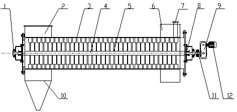
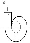
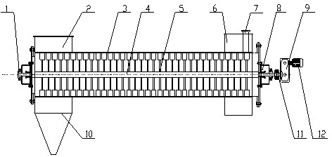
[0021] The structure of the sludge rake drying device is that a left bearing seat 1 and a right bearing seat 8 are respectively provided at both ends of the dryer housing 3, the rotating shaft 4 is located in the dryer housing 3, and the two ends are respectively arranged on the left bearing In the seat 1 and the right bearing seat 8; the part of the rotating shaft 4 located at one end of the right bearing seat 8 is connected to the output end of the reducer 9, and the input end of the reducer 9 is connected to the motor 12 through a coupling 11; at one end of the dryer housing 3 A drying medium inlet 6 and a sludge inlet 7 are arranged on the peripheral wall, a drying medium outlet 2 is arranged on the peripheral wall at one end of the dryer housing 3, a built-in gas-solid separator 10 is provided at the lower part of the drying medium outlet 2, and a Rake teeth 5 are arranged on the wall.

[0022] The drying heat medium enters the sludge rake dryer tangentially from the inle...


PUM


Abstract

The invention relates to a method for drying sludge and a drying device. A heat medium ( generally hot gas fume or hot air) for drying the sludge enters a sludge harrow type dryer from the tangential direction; wet sludge is added from one end of the harrow type dryer and is directly contacted with the heat medium in the drier to realize the drying process; the harrow type device can crush the block-shaped sludge and push the sludge from an inlet to an outlet; dry sludge is moved to the other end of the harrow type drier under the functions of the drying medium and the harrow type device and is separated from the drying medium through a function of an internal gas-solid separator and discharged out of the drier. The method has the characteristics that the drier can be securely and continuously operated, so that the obvious effects of high heat efficiency, low energy consumption and high yield are achieved.

Description

Technical field [0001] The present invention involves a sludge drying device and its drying method, which is a technical field of environmental protection equipment manufacturing. Background technique [0002] Lucky is the product of sewage treatment. The content of sludge organic matter is high, easy to rot, and has a strong odor, and contains heavy metals such as parasitic eggs, pathogenic microorganisms and copper, zinc, chromium, mercury and other heavy metals, Evil British, radioactive nucleo and other difficult to degrade toxic and harmful substances. If it is not properly processed, arbitrarily discharge will cause secondary pollution. [0003] At present, the treatment of sludge is mainly landfill and compost.Fitting and disposal will occupy a large amount of land resources, which can easily cause secondary pollution.According to the method of sterilization and maturity, the fertilizer effect and safety are different. This treatment method can achieve the purpose of resou...

Claims


Application Information

Patent Timeline
IPC IPC(8): C02F11/12
Inventor 郭宏伟鲁维加
Owner SOUTHEAST UNIV
Learn More