Reducing control mechanism of loom

A control mechanism and loom technology, applied in looms, circular looms, textiles, etc., can solve the problems of small diameter reduction range, limited space around the size ring, unable to realize dynamic change of fabric caliber, etc., and achieve convenient use. , Simple structure, low cost effect

Inactive Publication Date: 2012-09-19
DONGHUA UNIV +1
View PDF6 Cites 7 Cited by
  • Summary
  • Abstract
  • Description
  • Claims
  • Application Information

AI Technical Summary

Problems solved by technology

[0002] At present, there are few mechanisms for controlling the diameter of fabrics on circular looms, which are usually achieved by manually adjusting the blade or replacing the size ring, which cannot realize dynamic changes in fabric diameter.
The existing variable diameter control mechanism adopts two blades, and realizes the diameter reduction by controlling the radial position of the blades. Due to the limitation of the position of the blades, the actual range of diameter reduction is small
[0003] At present, there is a foreign patent No. US006679152B1 that involves a similar diameter-reducing mechanism, but the diameter-reducing mechanism in this patent is mainly suitable for knitting machines. The forming area is open over the entire plane
As a comparison, during the weaving process of the circular loom, the yarns are symmetrically opened up and down at the lower end of the size ring, the yarn at the upper end of the opening is higher than the plane of the size ring, and the yarn at the lower end is lower than the plane of the size ring, so around the fabric forming area, the size ring limited peripheral space
The variable diameter mechanism of this foreign patent will interfere with the warp yarn at the upper end of the opening, so it is not suitable for circular looms with symmetrical upper and lower warp openings

Method used


Image

  • Reducing control mechanism of loom
  • Reducing control mechanism of loom
  • Reducing control mechanism of loom

Examples


Embodiment Construction

[0017] Below in conjunction with specific embodiment, further illustrate the present invention. It should be understood that these examples are only used to illustrate the present invention and are not intended to limit the scope of the present invention. In addition, it should be understood that after reading the teachings of the present invention, those skilled in the art can make various changes or modifications to the present invention, and these equivalent forms also fall within the scope defined by the appended claims of the present application.

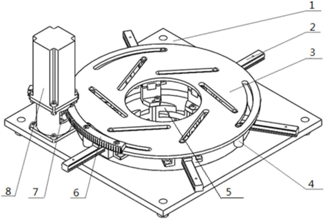
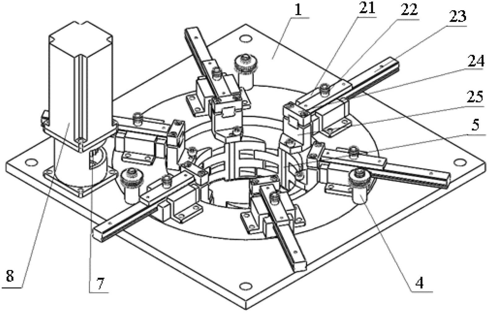
[0018] Embodiments of the present invention relate to a variable diameter control mechanism of a loom, such as figure 1 and figure 2 As shown, it includes a base 1 with an opening in the center, and several linear guide rail assemblies 2 are also provided on the base 1; the linear guide rail assemblies 2 are evenly distributed around the central opening with the central opening as the center of the circle, and the linear guid...


PUM


Abstract

The invention relates to a reducing control mechanism of a loom, comprising a base, wherein the base is provided with a plurality of linear guide rail assemblies, the linear guide rail assemblies are uniformly distributed by taking an opening at the center of the base as the center of a circle; the end part of each linear guide rail assembly is provided with a size ring; the size rings penetrate through the opening at the center of the base to be combined into a closed region below the base; a disk grooved cam provided with the opening at the center is erected on each linear guide rail assembly; the disk grooved cams are respectively provided with line grooves which are in one-to-one correspondence with the linear guide rail assemblies; pin shafts of the linear guide rail assemblies are arranged in the line grooves and can slide along the line grooves; incomplete gears are arranged on the circumference of each disk grooved cam; rotation centers of the incomplete gears are coincided with the rotation centers of the disk grooved cams, and the incomplete gears are driven to rotate along axis of the disk grooved cams by virtue of a motor. By adopting the reducing control mechanism of the loom disclosed by the invention, dynamic control on the calibre of a fabric on a circular weaving machine can be realized.

Description

technical field [0001] The invention relates to a diameter changing mechanism of a loom in the technical field of textile machinery, in particular to a diameter changing control mechanism of a loom. Background technique [0002] At present, there are few mechanisms for controlling the diameter of fabrics on circular looms, which are usually realized by manually adjusting the knife plate or changing the size ring, which cannot realize dynamic changes in fabric diameter. The existing variable diameter control mechanism adopts two blades, and realizes diameter reduction by controlling the radial position of the blades. Due to the limitation of the position of the blades, the actual range of diameter reduction is small. [0003] At present, there is a foreign patent No. US006679152B1 that involves a similar diameter-reducing mechanism, but the diameter-reducing mechanism in this patent is mainly suitable for knitting machines. The forming area is open over the entire plan. As ...

Claims


Application Information

Patent Timeline
Patent Type & Authority Applications(China)
IPC IPC(8): D03D51/02D03D37/00D04C3/38
Inventor 毛立民叶小鹏孙志宏周其洪周申华黎想周骏彦苏继伟
Owner DONGHUA UNIV
Why Eureka
Try Eureka