
Traveling type automatic material loading patching machine device

An automatic feeding and spraying machine technology, which is applied in the processing of building materials, construction, building construction, etc., can solve the problems of small loading hopper capacity, difficulty in coordination, and affecting construction safety, etc., and achieve reduction in stroke, cylinder diameter and Stroke optimization, the effect of solving the contradiction between thrust and stroke

Inactive Publication Date: 2014-09-17
FUJIAN FANGZHENG MACHINERY CO LTD
View PDF8 Cites 2 Cited by
  • Summary
  • Abstract
  • Description
  • Claims
  • Application Information

AI Technical Summary

Problems solved by technology

[0003] 1. Since the two hydraulic cylinders are arranged outside the loading hopper to be lifted, the cylinder body and the push rod of the two hydraulic cylinders are respectively hinged with the vehicle body and the loading hopper, so the loading hopper will be affected by the width of the vehicle body and the outer hydraulic cylinder. Due to the limitation, the width of the hopper cannot exceed the width of the car body, resulting in a small capacity of the loading hopper, which is not convenient for unloading construction of large dump trucks; when the capacity of the loading hopper is designed to be larger, the width of the car body also needs to be designed larger. It will also make the structure of the car body more complex and bulky
[0004] 2. The charging hopper of the spraying machine is hinged on the vehicle body beside the feed port of the spraying machine. The cylinder body and the push rod of the hydraulic cylinder are respectively hinged with the vehicle body and the loading hopper (forming a three-link structure). The expansion and contraction of the push rod of the oil cylinder makes one end of the loading hopper lift and tilt to realize loading. Since the two hydraulic cylinders are installed on both sides of the loading hopper, the width of the loading hopper is limited (note: the width of the loading hopper can only reach 2.3- -2.6m or so), in order to achieve the specified hopper capacity, the length of the hopper needs to be designed to be relatively large, so that the center of gravity of the hopper is far from the joint point between the hopper and the car body. In addition, because the tipping angle of the hopper does not exceed 90 As a result, the contradiction between the thrust and stroke of the hydraulic cylinder is difficult to coordinate, resulting in a larger cylinder diameter to meet the thrust requirements, and the cylinder stroke is too large (requires a push rod stroke of about 1.8 meters), and due to the limited installation size at the initial position, in In actual use, at least two or even more hydraulic cylinders are required to meet the requirements of the large stroke of the push rod (that is, the stroke requirement of the push rod is about 1.8 meters), but it will cause the working stability when lifting and turning the loading hopper Deviation, affecting construction safety
[0005] 3. In order to increase the capacity of the loading hopper of the shotcrete machine, it is necessary to add a rear fence (baffle) of a certain height at the rear opening of the loading hopper, so that when the dump truck unloads, it needs to be close to the rear fence (baffle) ) at the place where an inclined ladder for heightening can be added to allow the rear wheels of the dump truck to drive up and unload, which makes loading dangerous. If the inclined ladder is raised, the loading hopper will have less material and the loading will not be in place, which is not practical

Method used


Image

  • Traveling type automatic material loading patching machine device
  • Traveling type automatic material loading patching machine device

Examples


Embodiment Construction

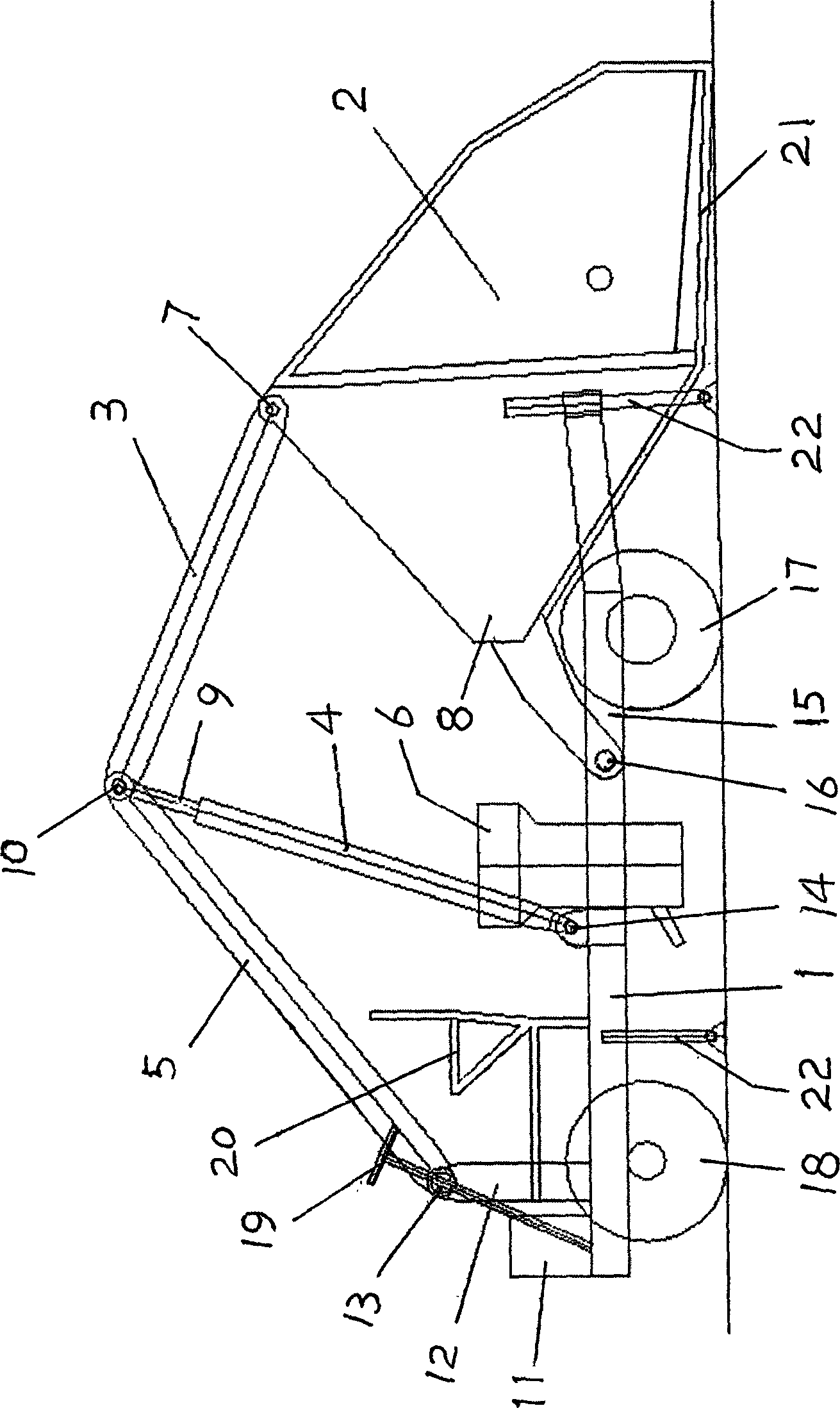
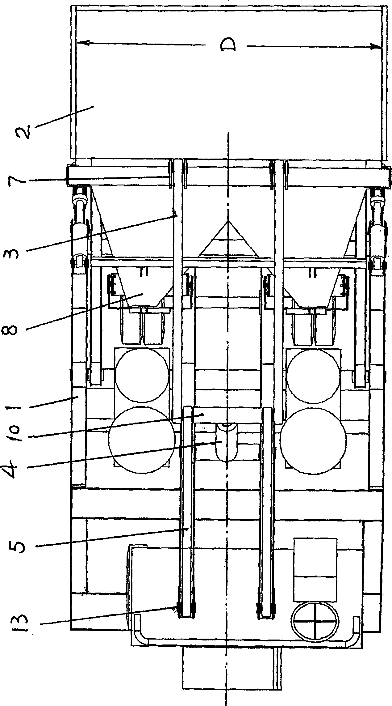
[0018] With reference to the accompanying drawings, it can be seen that the specific parts of this walking type automatic feeding spraying machine device of the present invention include: 1 ~ car body frame, 2 ~ loading hopper, 3 ~ pull rod (corresponding to the hinge point 7 above the loading hopper) Hinged), 4 ~ hydraulic cylinder (only one or two can be installed), 5 ~ connecting rod (hinged with the hinge point near the head of the car body), 6 ~ spraying machine, 7 ~ above the loading hopper Hinge point (hinged with one end of the pull rod), 8~the discharge end of the hopper, 9~the push rod of the hydraulic cylinder (hinged with the hinge point 10 of the pull rod and the connecting rod), 10~the hinge point of the tie rod and the connecting rod , 11 ~ the power transmission mechanism driving the car body (forming the driving system), 12 ~ the head of the car body, 13 ~ the hinge point at the head of the car body, 14 ~ the hinge point at the middle of the car body (located b...


PUM


Abstract

The invention relates to a traveling type automatic material loading patching machine device. The device comprises a device body rack, a charging hopper, a patching machine and a hydraulic pressure oil cylinder used for loading material. The device is characterized in that the charging hopper is in a hinged connection with a hinged joint point which is close to device body rear portion, the upper portion of the charging hopper is in a hinged connection with a hinged joint point which is close to the head portion of the device body sequentially through a pair of pull rods and a pair of connecting rods which are in the hinged connection, the hydraulic pressure oil cylinder is installed at the front of the charging hopper, a cylinder body of the hydraulic pressure oil cylinder is in a hinged connection with a hinged joint point which is close to the middle of the device body, a push rod of the hydraulic pressure oil cylinder is in a hinged connection with a hinged joint point of the pull rods and the connecting rods, and therefore a five-connecting rod charging mechanism composed of the device body rack, connecting rods, the hydraulic pressure oil cylinder, the push rod and the charging hopper is formed to load materials. According to the traveling type automatic material loading patching machine device, the complete device is beneficial to widening the charging hopper and substantially increasing the hopper capacity, and the hopper capacity can be increased by about 100%, lifting and turning performances are stable, the charging operation is convenient, the structure is simple, the device is energy-saving and environment-friendly, and the cost is low.

Description

(1) Technical field [0001] The invention relates to the design technology of a spraying machine in construction engineering, in particular to a walking type automatic feeding spraying machine device for spraying concrete. (2) Background technology [0002] Currently used in the construction site construction process, the spraying machine for concrete spraying and pouring generally adopts two methods of manual feeding or using a hydraulic cylinder to lift the hopper to load (refer to charging the spraying machine). Among them, manual feeding is intensive, and the concrete material is seriously leaked, and the entire construction period is affected because of the slow feeding speed. In order to improve the spraying work efficiency, the Chinese patent No. 201020252779.3 discloses a spraying machine that utilizes a hydraulic cylinder to lift the hopper to load materials. A loading hopper is hinged, and one end of the charging hopper is hinged to the side of the feed port of the...

Claims


Application Information

Patent Timeline
Patent Type & Authority Patents(China)
IPC IPC(8): E04G21/02
Inventor 林文建谢可兴丁达兴王孝雄
Owner FUJIAN FANGZHENG MACHINERY CO LTD
Learn More