
Carbon dioxide pressurizing conveying device

A technology for carbon dioxide and pressurized transportation, which is applied in the pipeline system, mechanical equipment, gas/liquid distribution and storage, etc. It can solve the problems of high noise of the piston rod of the pressurized cylinder, accelerated wear of the piston rod, and high reciprocating stroke frequency, so as to improve The effect of heat exchange efficiency, prolonging service life and improving work efficiency

Inactive Publication Date: 2012-09-19
江苏恒源碳创环境技术有限公司
View PDF5 Cites 7 Cited by
  • Summary
  • Abstract
  • Description
  • Claims
  • Application Information

AI Technical Summary

Problems solved by technology

[0003] In the existing carbon dioxide pressurized delivery device, during the process of starting the booster pump for pre-cooling, booster pump shutdown and maintenance, the low-pressure pipeline or high-pressure pipeline connected to the booster pump is depressurized and evacuated, and the escaped carbon dioxide is discharged into the atmosphere for the second time. polluted environment
Since the piston stroke of the booster cylinder is relatively short, in order to enable the booster pump connected to it to continuously and stably output high-pressure carbon dioxide, the reciprocating stroke frequency of the piston rod of the booster cylinder is relatively high, which results in accelerated wear of the piston rod and increased wear of the booster cylinder. The seals are prone to heat failure and other disadvantages, and the piston rod of the pressurized cylinder runs with relatively loud noise

Method used


Image

  • Carbon dioxide pressurizing conveying device
  • Carbon dioxide pressurizing conveying device
  • Carbon dioxide pressurizing conveying device

Examples


Embodiment Construction

[0014] The present invention will be further described below in conjunction with drawings and embodiments.

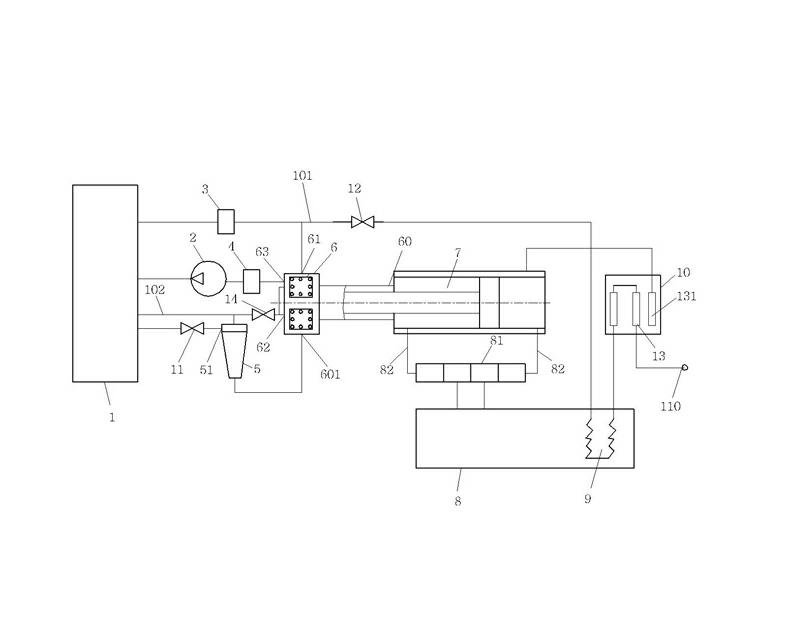
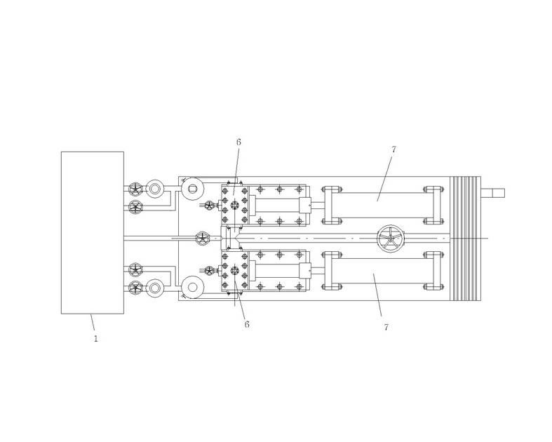
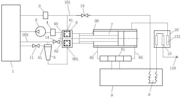
[0015] Such as figure 1 , figure 2 As shown, the present invention includes a carbon dioxide storage tank 1, a shielded pump 2, a high-voltage electronically controlled follow-up valve 3, a low-voltage electronically controlled follow-up valve 4, a liquid-gas separator 5, a carbon dioxide booster pump 6, a booster cylinder 7, a hydraulic general 8. The heat exchanger and the auxiliary heating tank 10, the carbon dioxide storage tank 1 is connected to the input end 51 of the liquid-gas separator through the input shut-off valve 11, and the liquid-phase output end 52 of the liquid-gas separator is connected to the input end 601 of the carbon dioxide booster pump. The high-pressure pipeline 101 of the first output end 61 of the carbon dioxide booster pump passes through the heat supply unit 13 of the air-energy heat pump heater of the auxiliary heating box 10 outside the...


PUM


Abstract

The invention discloses a carbon dioxide pressurizing conveying device. A carbon dioxide storage jar of the carbon dioxide pressurizing conveying device is connected with an input end of a liquid-gas separator; an output end of the liquid-gas separator is connected with an input end of a carbon dioxide booster pump; a first output end of the carbon dioxide booster pump is connected with a high-pressure carbon dioxide output end through a heat exchanger and an auxiliary heating box and is also connected with the carbon dioxide storage jar through a high-pressure electronic control servo valve;a second output end of the carbon dioxide booster pump is respectively connected with the output end of the liquid-gas separator and the carbon dioxide storage jar; and a third output end of the carbon dioxide booster pump is connected with the carbon dioxide storage jar through a low-pressure electronic control servo valve and a shielding pump. A high-pressure or low-pressure recycling pipeline is additionally arranged in the carbon dioxide pressurizing conveying device and carbon dioxide discharged during pumping halting and overhauling processes is recycled, so that the carbon dioxide is prevented from being secondarily discharged into atmosphere. The liquid-gas separator is used for performing liquid-gas separation on the mixed-phase carbon dioxide outputted by the carbon dioxide storage jar, so that the absorbing efficiency of the carbon dioxide booster pump is increased.

Description

technical field [0001] The invention relates to a carbon dioxide booster pump device, in particular to a delivery and discharge device for low-temperature liquid-phase carbon dioxide after pressurization and heating, and belongs to the technical field of environmental protection. Background technique [0002] The continuous increase of carbon dioxide emissions is an important reason for the greenhouse effect. The greenhouse effect has increased the number of pests and diseases on the earth, the sea level has risen, the climate has become abnormal, the ocean storms have increased, the land has become dry, and the desertification area has increased, which seriously affects the survival prospects of human beings. Reducing the emission of carbon dioxide, capturing and treating the emitted carbon dioxide is a major issue facing human beings that needs to be solved urgently. Pure gaseous carbon dioxide is separated from the captured industrial exhaust mixed gas ...

Claims


Application Information

Patent Timeline
IPC IPC(8): F17D1/02F17D3/01
Inventor 毛恒松杨军
Owner 江苏恒源碳创环境技术有限公司
Learn More