
Auxiliary device for wire cut electrical discharge machining

A technology of cutting processing and auxiliary devices, which is applied in the direction of electric processing equipment, accessory devices, metal processing equipment, etc., can solve the problems that the magnetic field strength and direction, and ultrasonic strength cannot be stable and consistent, so as to improve the processing quality, surface roughness, The effect of accelerated deionization

Active Publication Date: 2019-08-02
HUAZHONG UNIV OF SCI & TECH
View PDF4 Cites 0 Cited by
  • Summary
  • Abstract
  • Description
  • Claims
  • Application Information

AI Technical Summary

Problems solved by technology

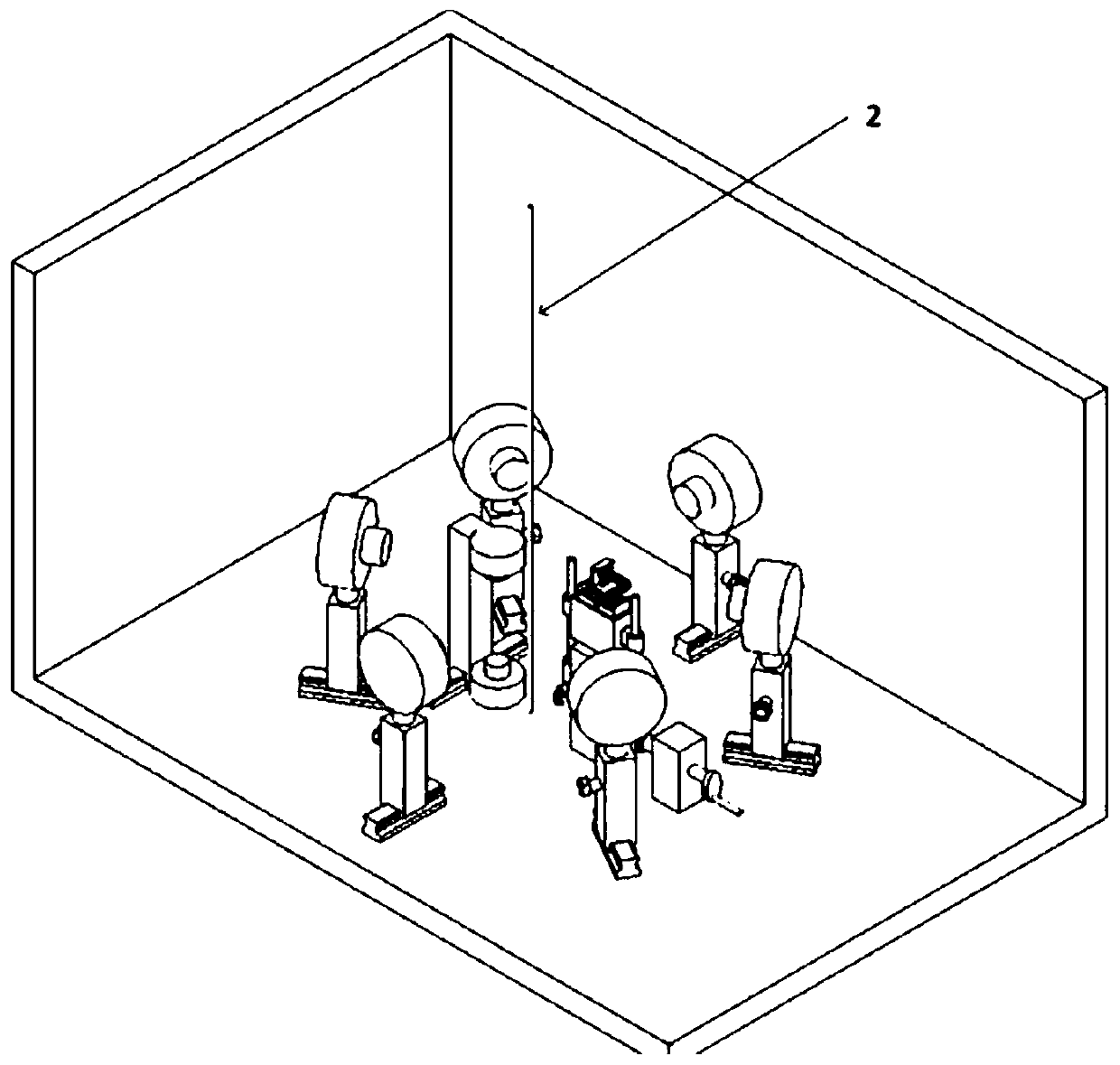
[0006] Aiming at the above defects or improvement needs of the prior art, the present invention provides an auxiliary device for wire electric discharge machining, the purpose of which is to construct The direction and intensity of the magnetic field are stable throughout the entire wire-cutting process. In addition, by setting the workpiece to be processed on the three-dimensional ultrasonic platform, the stability and consistency of the ultrasonic vibration during the entire wire-cutting process is guaranteed. This solves the problem that in the prior art, the magnetic field strength, direction and ultrasonic strength cannot be stable and consistent in ultrasonic magnetic field assisted EDM

Method used


Image

  • Auxiliary device for wire cut electrical discharge machining
  • Auxiliary device for wire cut electrical discharge machining
  • Auxiliary device for wire cut electrical discharge machining

Examples


Embodiment 1

[0060] Processing environment: The wire cutting machine is a high-performance 5-axis CNC slow-moving wire-cut electric discharge machine tool. The metal workpiece to be processed is a difficult-to-machine material titanium alloy Ti6Al4V with a thickness of 10 mm;

[0061] The pulse current provided by the machine tool has a pulse width of 22μs and a current of 5A; the slit with a length of 5mm is cut; the DC excitation power supply of the auxiliary device used has the function of current overvoltage and overtemperature protection, the accuracy of the power supply current is 10mA, and can provide current 0~10A, voltage 0 ~ 30V DC, output power 300W; the electromagnet of the auxiliary device includes magnetic poles, yokes (including vertical yokes and cross yokes), wire wraps and column sleeves, all of which are made of industrial pure iron, and the distance between wire wraps is 80mm. The diameter of the magnetic pole head is 12mm, and the distance between the two magnetic poles...

Embodiment 2

[0064] Processing environment: The wire cutting machine is a high-performance 5-axis CNC slow-moving wire-cut electric discharge machine tool. The metal workpiece to be processed is aluminum-based silicon carbide, a metal-based composite material with a thickness of 10 mm.

[0065] The pulse current provided by the machine tool has a pulse width of 22μs and a current of 5A; the slit with a length of 5mm is cut; the DC excitation power supply of the auxiliary device used has the function of current overvoltage and overtemperature protection, and the accuracy of the power supply current is 10mA, which can provide current 0~10A, DC voltage of 0-30V, output power 300W; the electromagnet of the auxiliary device includes magnetic poles, yokes (including vertical yokes and cross yokes), wire wraps and column sleeves, all made of industrial pure iron, and the distance between wire wraps is 80mm. The diameter of the ferromagnetic pole head is 12mm, and the distance between the two magne...

Embodiment 3

[0068] The difference between the processing environment of embodiment 3 and embodiment 1 is: the processed material is 10mm thick hard alloy, the electrode wire adopts the common copper wire that diameter is 0.15mm, the rotating speed of electromagnet group is 15r / min, ultrasonic The power of the converter is 150W, the vibration frequency of the three platforms is 15KHz, the amplitude is 30μm, the magnetic induction intensity provided by the auxiliary device is 400mT, the pulse current pulse width provided by the machine tool is 22μs, and the current is 2A. Others are the same as in Example 1 same.

[0069] After adopting the auxiliary device provided by this embodiment, the material removal rate is 0.083mm 3 / min, the surface roughness of the obtained workpiece is 0.52 μm; and without the auxiliary device provided by this embodiment, the material removal rate is 0.017mm 3 / min, the surface roughness of the obtained workpiece is 0.58 μm; in contrast, the use of the auxiliary...


PUM

PropertyMeasurementUnit
diameteraaaaaaaaaa
diameteraaaaaaaaaa
diameteraaaaaaaaaa

Abstract

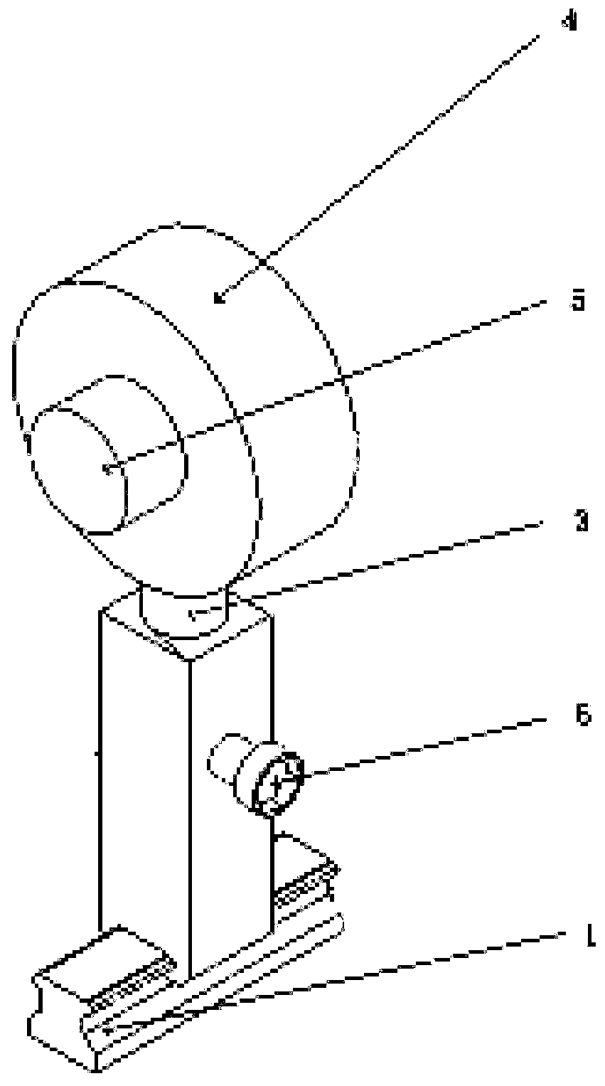
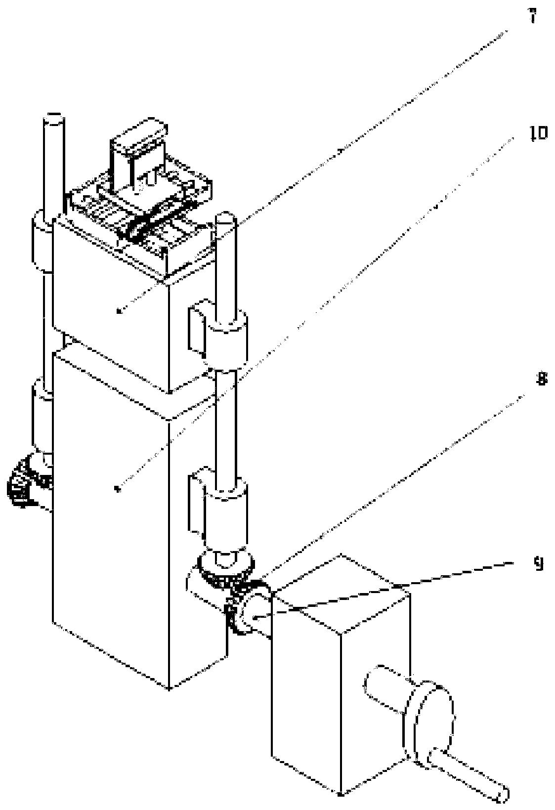
The invention discloses an auxiliary device for wire cut electrical discharge machining; a magnetic field perpendicular to the machining direction, a magnetic field perpendicular to the electrode wiredirection and a magnetic field perpendicular to the ground can be synchronously applied in the wire cut electrical discharge machining process; and workpieces can be clamped on a three-degree-of-freedom ultrasonic vibration platform. The device comprises a horizontal magnetic field electromagnet, a vertical magnetic field electromagnet and an ultrasonic transducer; the horizontal magnetic field electromagnet and the vertical magnetic field electromagnet can move along guide rails along with movement of electrode wires in the machining process; and the electromagnets are controlled to move along the guide rails to change the distance between two magnetic poles, so that the magnetic field intensity in the machining position can be not changed. The power of the ultrasonic transducer is controlled to ultrasonically vibrate the workpieces; and the vibration amplitude and the frequency can be adjusted to stably and reliably remove residues. The device can build stable and consistent magnetic field intensity, magnetic field direction and ultrasonic vibration intensity in the whole machining process, and provides stable and excellent wire cut electrical discharge machining auxiliary conditions.

Description

technical field [0001] The invention belongs to the technical field of wire electric discharge machining for special processing, and more specifically relates to an auxiliary device for wire electric discharge machining. Background technique [0002] With the development of modern industry, the quality requirements for mechanical products are getting higher and higher. It is difficult for traditional processing methods to meet the processing requirements of various ultra-precision, new materials with complex surfaces, and new structures. Special processing methods are required to process these Materials or structures are processed. Special processing is characterized by non-mechanical contact, no macroscopic cutting force, but a processing method that uses non-mechanical energy (light, electricity, magnetism, heat, chemistry, etc.) to remove materials. [0003] Wire EDM is a special processing method that uses electric energy to process metal materials. It is a processing m...

Claims


Application Information

Patent Timeline
Patent Type & Authority Applications(China)
IPC IPC(8): B23H1/00B23H7/02B23H11/00
CPCB23H1/00B23H7/02B23H11/00
Inventor 张臻张国军于海深
Owner HUAZHONG UNIV OF SCI & TECH
Learn More