
A composite ignition circuit

An ignition circuit and composite technology, which is applied in the professional field of aerospace propulsion technology, can solve the problems of semiconductor spark plug end surface pollution, output voltage easy to jitter, high-voltage switch selection difficulties, etc., to ensure ignition reliability and reduce end area pollution , The effect of suppressing the secondary voltage oscillation

Active Publication Date: 2019-08-09
BEIJING RES INST OF PRECISE MECHATRONICS CONTROLS +1
View PDF11 Cites 0 Cited by
  • Summary
  • Abstract
  • Description
  • Claims
  • Application Information

AI Technical Summary

Problems solved by technology

Conventional ignition circuits usually adopt capacitive direct ignition or high-voltage pulse ignition. The former has large ignition energy, but the selection of high-voltage switches is difficult, which limits the input voltage amplitude; short
[0004] Most of the research results at this stage are pulse transformer ignition. This method has low ignition energy, which is likely to cause contamination of the end surface of the spark plug outside the semiconductor and reduce the service life. Circuits of Devices", Beijing University of Aeronautics and Astronautics, Wei Qiang, etc., authorized announcement number CN 101943148B / 2011.12.07
There is also a composite pulse ignition circuit using the principle of negative energy storage. Since the pulse transformer has no clamping circuit in the primary stage, a high-voltage thyristor must be used, and the secondary output has no secondary energy storage capacitor, and the output voltage is prone to jitter. Therefore, this type The circuit is also only suitable for external spark plug ignition with inaccurate ignition control. For details, see the master's degree thesis of the Chinese Academy of Sciences "Research on the Performance of 40J Pulsed Plasma Thruster", Hu Zongsen, P17~21, 2002.6

Method used


Image

  • A composite ignition circuit
  • A composite ignition circuit

Examples


Embodiment Construction

[0027] Below in conjunction with accompanying drawing and specific embodiment the present invention is described in further detail:

[0028] The invention provides a composite ignition circuit, which has the advantages of large ignition energy, no need for a high-voltage switch, no pollution accumulation, and long service life of an external spark plug.

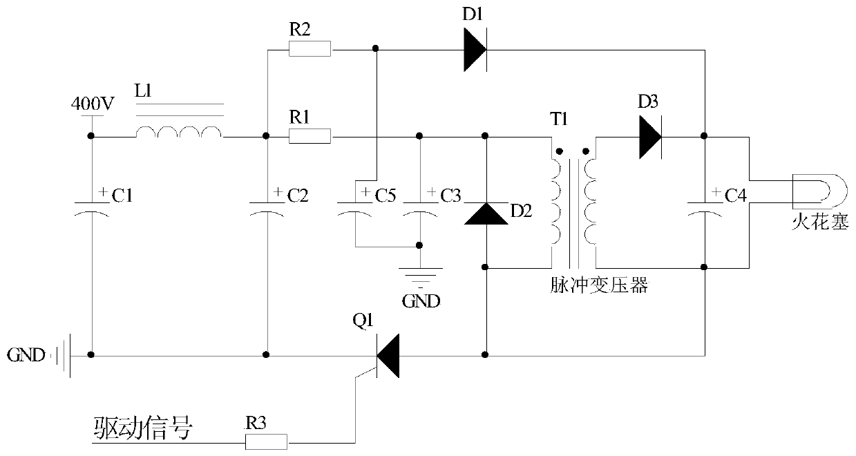
[0029] Such as figure 1 Shown is a schematic diagram of a composite ignition circuit. As can be seen from the figure, a composite ignition circuit includes a first resistor R1, a second resistor R2, a third resistor R3, a first capacitor C1, a second capacitor C2, and a third capacitor C3 , the fourth capacitor C4, the fifth capacitor C5, the first diode D1, the second diode D2, the third diode D3, the inductor L1, the transformer T1 and the MOS transistor Q1;

[0030] Wherein, one end of the first capacitor C1 is connected to an external power supply, and the other end of the first capacitor C1 is grounded; one end of the i...


PUM


Abstract

The invention discloses a composite ignition circuit, and relates to the professional field of the aerospace propulsion technology. The composite ignition circuit includes a first resistor R1, a second resistor R2, a third resistor R3, a first capacitor C1, a second capacitor C2, a third capacitor C3, a fourth capacitor C4, a fifth capacitor C5, a first diode D1, a second diode D2, a third diode D3, an inductor L1, a transformer T1 and an MOS tube Q1. The composite ignition circuit adopts an interleaved double redundant design ignition circuit driver board, and the ignition reliability is ensured; a high-performance single-chip digital circuit is used for replacing a logic gating circuit to generate a double-circuit pulse ignition signal, the manual / auto-ignition function switching and thepulse frequency adjustment are realized at the same time, metallic shielding of a control circuit is realized, and the magnetic isolation of the ignition signal and the driver board is realized; andthe composite ignition circuit has the advantages of large ignition energy, no need for a high-voltage switch, less dirt retention and long service life of an external spark plug.

Description

technical field [0001] The invention relates to the professional field of aerospace propulsion technology, in particular to a composite ignition circuit. Background technique [0002] The propulsion device is the source of power for the spacecraft to escape the gravitational shackles of the earth and enter space. Electric propulsion devices have become the preferred propulsion system for future spacecraft due to their high specific impulse and long life. my country has successively carried out space flight verification of Hall and ion-type electric propulsion. Compared with gas fuel electric propulsion (such as Hall and ion type) systems, solid ablative pulsed plasma thrusters (Pulsed Plasma Thruster, PPT) have the advantages of stable and easy storage of solid working fluid, no need for storage tanks and pipelines, and convenient The advantage of integrating with spacecraft has become a new hotspot in the development of electric propulsion technology. The ignition circuit...

Claims


Application Information

Patent Timeline
Patent Type & Authority Patents(China)
IPC IPC(8): F03H1/00
CPCF03H1/0006F03H1/0087
Inventor 赵絮杨磊张益齐王令岩蒋建文
Owner BEIJING RES INST OF PRECISE MECHATRONICS CONTROLS
Learn More