Heat pipe vacuum liquid filling and degassing method and equipment adopting same

A technology for degassing equipment and heat pipes, which is applied in the field of heat pipe vacuum liquid filling and degassing methods and equipment, can solve the problems of wasting metal materials, loss of working fluid, etc., and achieve high production efficiency, high precision, and simple and easy technical means Effect

Inactive Publication Date: 2012-09-19
SOUTH CHINA UNIV OF TECH
View PDF8 Cites 20 Cited by
  • Summary
  • Abstract
  • Description
  • Claims
  • Application Information

AI Technical Summary

Problems solved by technology

The disadvantage is that it is greatly affected by the environment, and there will be loss of working fluid, and the copper pipe needs to reserve a certain length as the gas-gathering section to cut off, wasting metal materials

Method used


Image

  • Heat pipe vacuum liquid filling and degassing method and equipment adopting same
  • Heat pipe vacuum liquid filling and degassing method and equipment adopting same
  • Heat pipe vacuum liquid filling and degassing method and equipment adopting same

Examples


Embodiment

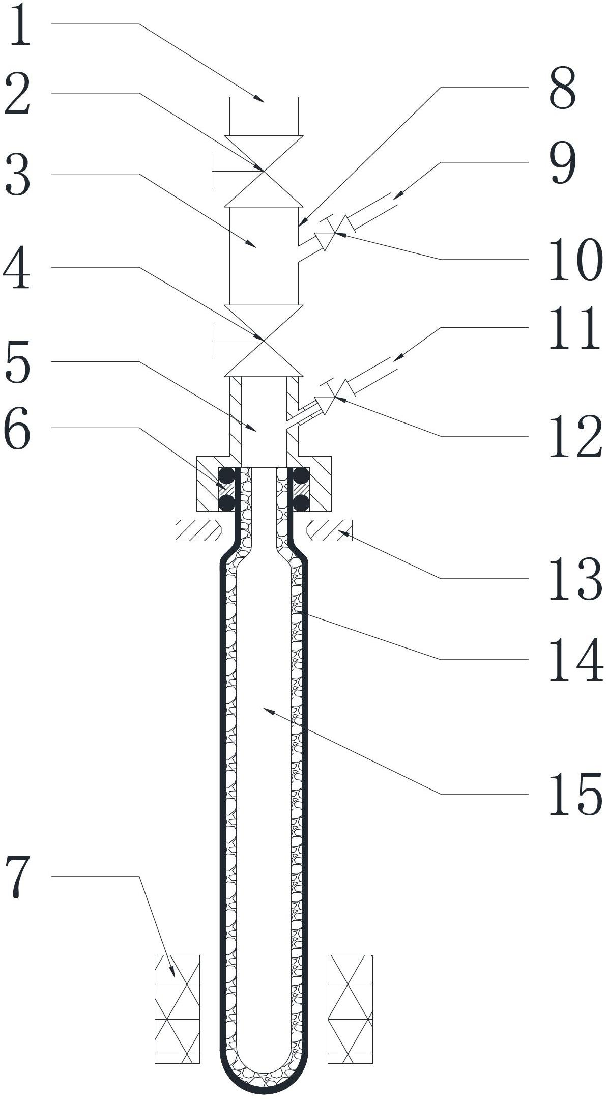
[0020] Such as figure 1 shown. The heat pipe vacuum filling and degassing equipment of the present invention includes a vacuum system 1, a perfusion system 11, an action pipeline 8, a heating module 7 and a sealing mold 13. An electromagnetic valve 4 is arranged in the middle of the action pipeline 8, and the action pipeline 8 is covered by the electromagnetic valve. The valve 4 is divided into upper chamber 3 and lower chamber 5. The vacuum system 1 is connected to the upper chamber 3 of the action pipe 8 by a vacuum solenoid valve 2. The perfusion system 11 is connected to the lower chamber 5 of the action pipe 8 by a needle valve 12. The sealing mold 13 is arranged on the nozzle side of the heat pipe 15 to be processed, and the heating module 7 is arranged at the tail of the heat pipe 15 to be processed.

[0021] The upper chamber 3 is connected with an air source 9 and is provided with a shut-off valve 10 for controlling its on-off.

[0022] The lower cavity 5 is provide...


PUM


Abstract

The invention relates to a heat pipe vacuum liquid filling and degassing method and equipment adopting the same. The heat pipe vacuum liquid filling and degassing equipment includes a vacuum system, a perfusing system, a heating module and a sealing die, wherein an electromagnetic valve is arranged in the middle of an action pipeline; the action pipeline is divided into an upper cavity and a lower cavity through the electromagnetic valve; the vacuum system is connected with the upper cavity of the action pipeline through a vacuum electromagnetic valve; the perfusing system is connected with the lower cavity of the action pipeline through a micro needle valve; the sealing die is arranged adjacent to the orifice of the to-be-processed heat pipe; and the heating module is arranged at the tail part of the to-be-processed heat pipe. According to the heat pipe vacuum liquid filling and degassing method, the to-be-processed heat pipe internally provided with a capillary structure sequentially vacuumizes, perfuses the working medium and separates the remaining non condensable gas. The heat pipe vacuum liquid filling and degassing method and equipment have simple and easy technical means, high production efficiency and high working medium filling precision, and save metal materials.

Description

technical field [0001] The invention relates to the technical field of heat pipe filling with working medium and removal of non-condensable gas in a vacuum environment, in particular to a heat pipe vacuum liquid filling and degassing method and equipment thereof. Background technique [0002] With the rapid development of IC manufacturing technology, the number of transistors integrated on a single chip has reached hundreds of millions, the power consumption and chip connection density are getting higher and higher, and the heat dissipation area is small, which makes the heat flux density increase sharply and the chip temperature rise significantly. Affect its working reliability and service life. Therefore, micro heat pipes with the characteristics of high thermal conductivity, high reliability, fast thermal response, and no need for additional electric drive have become ideal heat conduction components commonly used in the fields of aviation and optoelectronics. [0003] ...

Claims


Application Information

Patent Timeline
Patent Type & Authority Applications(China)
IPC IPC(8): F28D15/04
Inventor 李勇何成彬曾志新
Owner SOUTH CHINA UNIV OF TECH
Why Eureka
Try Eureka