Field observation facility for radial-flow experiment site suitable for seasonally frozen-melted region

An experimental field and seasonal technology, applied in the field of field observation, can solve problems such as difficult to meet the conditions of use, increase of observation data errors, and less attention to lateral migration, so as to facilitate real-time observation and research, ensure normal operation, and resist soil freezing The effect of swelling damage

Inactive Publication Date: 2012-09-19
程红光
View PDF6 Cites 2 Cited by
  • Summary
  • Abstract
  • Description
  • Claims
  • Application Information

AI Technical Summary

Problems solved by technology

In the design of the traditional runoff experimental field, the boundary, the collecting tank and the water collecting tank are made of concrete materials. Due to the phenomenon of frost heaving and deformation, it is difficult to meet the use conditions of the seasonal freeze-thaw areas in northern my country, and its porous gel structure cannot Avoid the loss of water leakage and increase the error of observation data
Most of the traditional runoff test sites focus on the observation of slope runoff, but pay less attention to the lateral migration of water after infiltration into the vadose zone. Stratified sampling processing, because the change of soil microstructure with the increase of soil depth will affect the migration process of soil water, which requires different treatment for the study of soil lateral seepage water migration at different depths
The observation items of the general runoff experiment field focus on rainfall, surface runoff, soil erosion, runoff erosion, etc., but rarely involve the migration and loss of nutrients in the soil driven by hydrological processes

Method used


Image

  • Field observation facility for radial-flow experiment site suitable for seasonally frozen-melted region
  • Field observation facility for radial-flow experiment site suitable for seasonally frozen-melted region
  • Field observation facility for radial-flow experiment site suitable for seasonally frozen-melted region

Examples


Embodiment Construction

[0029] In order to make the technical problems, technical solutions and beneficial effects solved by the present invention clearer, the present invention will be further described in detail below in conjunction with the accompanying drawings and embodiments. It should be understood that the specific embodiments described here are only used to explain the present invention, not to limit the present invention.

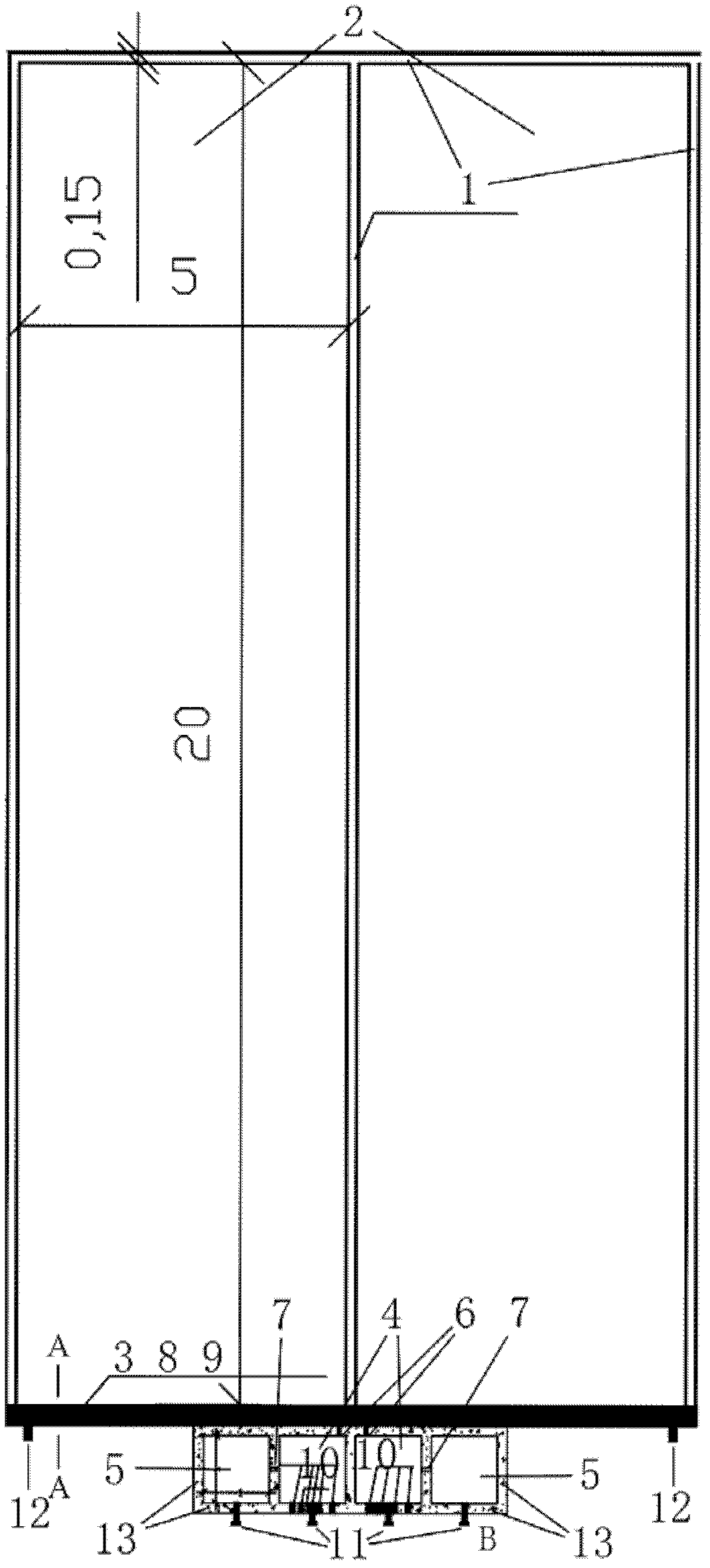
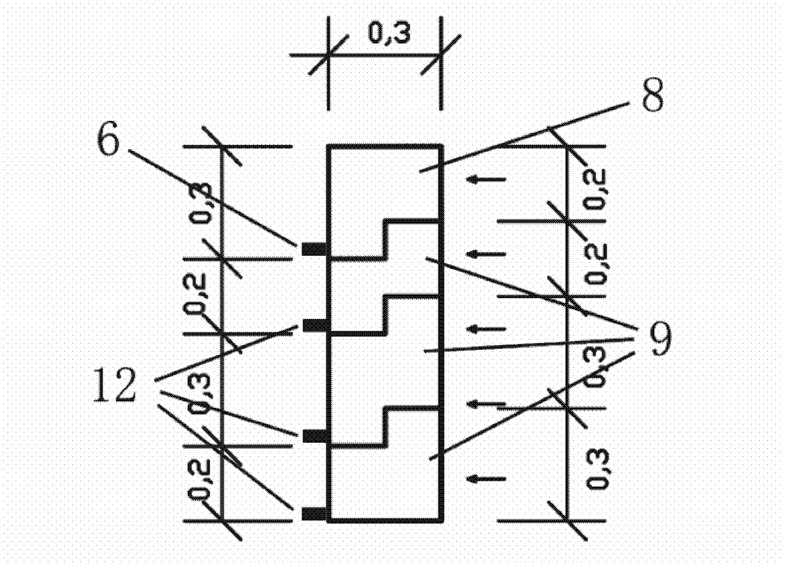
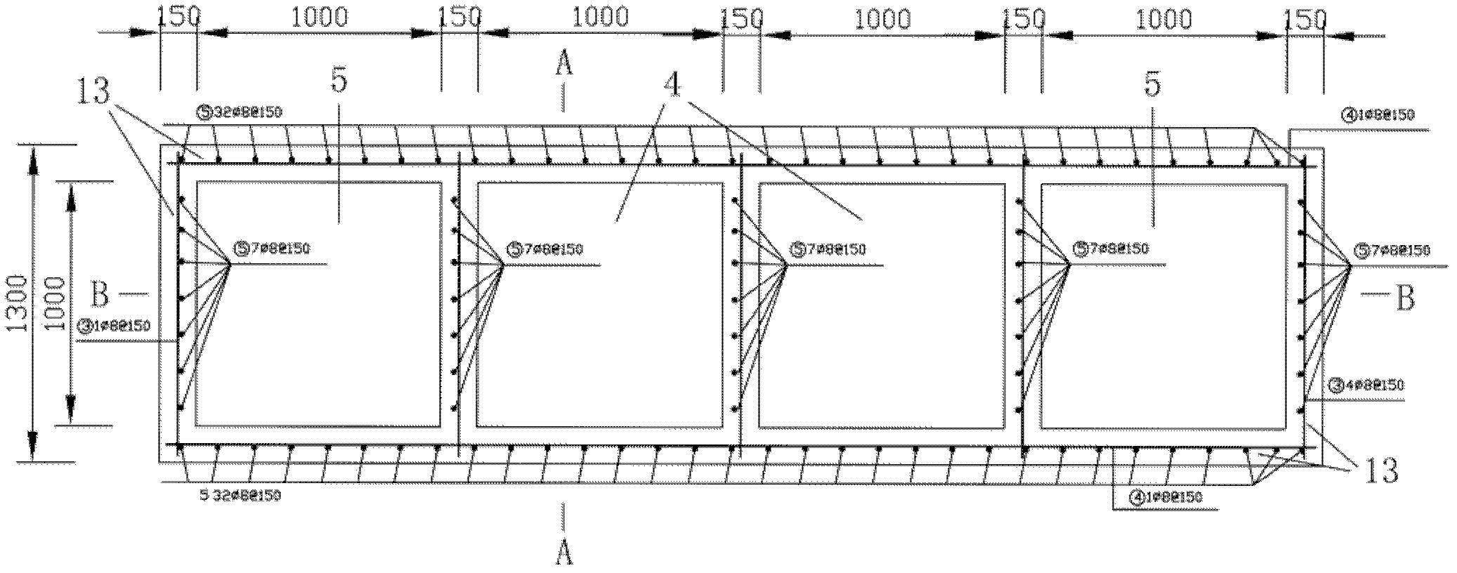
[0030] like Figure 1 to Figure 5 The facility shown is suitable for field observation runoff experiment field in seasonal freeze-thaw areas, including at least one level of slope experiment field system; the slope experiment field system of each level includes slope surface experiment field, surface runoff and soil side seepage collection device, diversion tank and water collection box; the boundary of the slope experiment site is provided with a horizontal fence, the surface runoff and soil side seepage water collection device and two vertical fences on the left and ri...


PUM


Abstract

The invention discloses a field observation facility for a radial-flow experiment site suitable for a seasonally frozen-melted region. A transverse wall, a surface runoff and soil lateral seepage collecting device, a left longitudinal wall and a right longitudinal wall are arranged at the borders of a slope experiment site and surround to form an experiment farmland, wherein the transverse wall is located at the upper border of the slope experiment site; the longitudinal walls extend to the surface runoff and soil lateral seepage collecting device along the slope of the slope experiment site; the surface runoff and soil lateral seepage collecting device is vertical to the surface runoff flow direction of the slope experiment site, is arranged at the lower border of the slope experiment site, and is as wide as the slope experiment site; and a diversion pool and a water tank are located in the downslope direction of the surface runoff and soil lateral seepage collecting device. The field observation facility for the radial-flow experiment site meets the field observation for hydrologic process and soil erosion under both the rainfall and snowmelt conditions, and can effectively resist the damage from soil frost heaving and ensure the normal running of the experiment site.

Description

technical field [0001] The patent of the present invention relates to the technical field of field observation of hydrological process-nutrient migration law under the condition of rainfall or snowmelt in seasonal freeze-thaw areas, especially relates to a facility suitable for field observation runoff experiment field in seasonal freeze-thaw areas . Background technique [0002] The runoff experimental field is a key scientific research facility and observation method for quantitatively studying the hydrological process and soil erosion process of a watershed or slope. The basic observation data obtained from it play an important role in the study of small-scale soil erosion laws and then extended to the prevention and control of regional water and soil erosion. The construction of the runoff experiment field is restricted by terrain, climate and other conditions, so the design schemes of the runoff experiment field are different in different regions. In the design of the ...

Claims


Application Information

Patent Timeline
Patent Type & Authority Applications(China)
IPC IPC(8): G01N33/24
Inventor 程红光郝芳华蒲晓丁兆亮王东利路路
Owner 程红光
Why Eureka
Try Eureka