Polarity determining device of direct plug-in type two-pin semiconductor

A polarity judgment and semiconductor technology, which is applied in the field of in-line two-pin semiconductor polarity judgment devices, can solve the problems of inability to insert semiconductor electronic components into PCB, difficult state judgment, low production efficiency, etc., so as to reduce machine and labor costs, Low cost and the effect of reducing intermediate links

Inactive Publication Date: 2014-11-26
SHENZHEN LIANSHUO AUTOMATION TECH
View PDF8 Cites 0 Cited by
  • Summary
  • Abstract
  • Description
  • Claims
  • Application Information

AI Technical Summary

Problems solved by technology

[0002] Since the states of semiconductor bulk materials include positive direction, reverse direction, short circuit and open circuit, it is difficult to distinguish the state during online high-speed testing. Therefore, the traditional plug-in machine can only tape various horizontal semiconductor electronic A predetermined sequence program is inserted into the PCB (circuit board), and then the feet are bent and cut, but the bulk semiconductor electronic components cannot be automatically inserted into the PCB; that is, in the prior art, the bulk materials must be braided into 52mm, spacing 5mm and parallel perpendicularity ± 0.5mm braiding materials can be used, resulting in low production efficiency and high labor costs

Method used


Image

  • Polarity determining device of direct plug-in type two-pin semiconductor
  • Polarity determining device of direct plug-in type two-pin semiconductor
  • Polarity determining device of direct plug-in type two-pin semiconductor

Examples


Embodiment 1

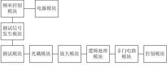
[0045] Such as figure 1 and figure 2 As shown, this example provides an in-line two-pin semiconductor polarity judging device, including:

[0046] A power module for providing electricity;

[0047] a frequency control module, the frequency control module is connected to the power module;

[0048] A test signal generation module, the test signal generation module is connected with the frequency control module, and is used to output a pair of alternating square wave test signals with opposite polarities;

[0049] A test module, the test module is connected with the test signal generation module, and the test point is passed through the current of the alternating square wave test signal, and the test square wave pulse signal is output;

[0050] An optocoupler module, the optocoupler module is connected with the test module, and converts the test square wave pulse signal into a reverse signal;

[0051] an amplifying module, the amplifying module is connected with the optocoup...

Embodiment 2

[0063] Different from Embodiment 1, the logic processing module described in this embodiment is a single-chip microcomputer. A single-chip microcomputer is used to carry out logical processing on the amplified reverse signal, the processing speed is fast, the control is simple and easy to operate, and the single-chip microcomputer can also be an MCU.

[0064] A further improvement of this example is that the test signal generating module includes a monostable trigger, a multivibrator and a digital square wave generator. Under the action of the external pulse, the monostable trigger can turn over from a stable state to a transient stable state, and return to the original stable state after maintaining the transient state for a period of time; The resonant oscillator makes the two electronic devices turn on and off alternately through resistance-capacitance coupling, thereby self-excited to generate a square wave output. The test signal generation module includes a monostable tr...

Embodiment 3

[0070] The difference from Embodiment 1 or 2 is that the test signal generation module in this example outputs a pair of 5KHz alternating square wave test signals with a peak voltage of 9V.

[0071] The test signal generation module outputs a pair of alternating square wave test signals from 1KHz to 5KHz, which can ensure that the test signal does not generate delay and prevent data loss. The frequency of the alternating square wave test signal is preferably 5KHz, which ensures its test state Accuracy, improve the efficiency of semiconductor polarity testing and bulk material testing, especially suitable for logic processing modules using single-chip microcomputers.

[0072] The peak voltage of the alternating square wave test signal depends on the peak voltage of the power module, which can be a voltage drop with the peak voltage of the power module, such as 0.6V. The peak voltage of the alternating square wave test signal described in this example is the power module The pea...


PUM


Abstract

The invention provides a polarity determining device of a direct plug-in type two-pin semiconductor. The device comprises a power supply module, a frequency control module, a testing signal generation module, a test module, an optocoupler module, an amplifying module, a logic processing module, a NOT gate circuit module and a control module, wherein the testing signal generation module is connected with the frequency control module and used for outputting a pair of alternate square wave testing signals with opposite polarities; the test module outputs testing square wave pulse signals after current which passes through the alternate square wave testing signals passes through a test point; the optocoupler module converts the testing square wave pulse signals into backward signals, the amplifying module is used for amplifying the backward signals; the logic processing module converts the amplified backward signals into digital signals logically; the NOT gate circuit module amplifies the digital signals reversely and outputs driving current; and the control module controls the semiconductor according to testing states of the semiconductor. During online high-speed testing, a state of a semiconductor bulk material can be identified accurately, the direction of the bulk material is accurately led into a feeding channel, and misdirection, short circuit and open circuit are avoided.

Description

technical field [0001] The invention relates to the field of semiconductor polarity judgment, in particular to an in-line two-pin semiconductor polarity judgment device. Background technique [0002] Since the states of semiconductor bulk materials include positive direction, reverse direction, short circuit and open circuit, it is difficult to distinguish their states during online high-speed testing. Therefore, traditional plug-in machines can only tape various horizontal semiconductor electronic components A predetermined sequence program is inserted into the PCB (circuit board), and then the feet are bent and cut, but the bulk semiconductor electronic components cannot be automatically inserted into the PCB; that is, in the prior art, the bulk materials must be braided into 52mm, spacing 5mm and parallel perpendicularity ± 0.5mm braiding materials can be used, resulting in low production efficiency and high labor costs. Contents of the invention [0003] The technica...

Claims


Application Information

Patent Timeline
Patent Type & Authority Patents(China)
IPC IPC(8): G01R31/02G01R31/26
Inventor 杨娅姜敏刘鑫张维伦刘丽梅
Owner SHENZHEN LIANSHUO AUTOMATION TECH
Why Eureka
Try Eureka