Current control method for active power filter

A power filter, current control technology, applied in active power filter, harmonic reduction device, AC network to reduce harmonic/ripple and other directions, can solve the problems of slow response, large switching frequency fluctuation, low precision and so on , to achieve the effect of small current following error range, fast dynamic response speed and good filtering

Inactive Publication Date: 2012-09-19
RUGAO TOTEM ELECTRIC POWER TECH
View PDF0 Cites 10 Cited by
  • Summary
  • Abstract
  • Description
  • Claims
  • Application Information

AI Technical Summary

Problems solved by technology

The switching frequency of the former is fixed, but the response is slow and the precision is low; while the latte

Method used


Image

  • Current control method for active power filter
  • Current control method for active power filter
  • Current control method for active power filter

Examples


Embodiment 1

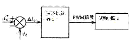
[0026] figure 1 To take the control of one phase as an example, the schematic diagram of the instantaneous value comparison method of the hysteresis comparator 1 is used. In this method, the command signal ic of the compensation current is * Compared with the actual compensation current signal ic, the deviation △ic between the two is used as the input of the hysteresis comparator 1, and the hysteresis comparator 1 generates a PWM signal to control the on-off of the main circuit, and the PWM signal is transmitted by the drive circuit 2 Control the on and off of the switch, thereby controlling the change of the compensation current ic.

Embodiment 2

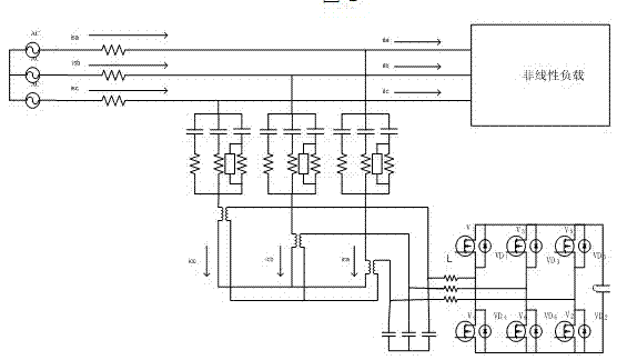
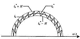
[0028] Let's take phase a as an example for further discussion, let the direction of ic be as follows figure 2 Shown; When the V1 device (IGBT or diode) is turned on, ic will decrease; and when the V4 device is turned on, ic will increase. Use H to represent the bandwidth of the hysteresis comparator 1, the working principle of the hysteresis comparator 1 is as follows image 3 As shown, when When , the output of hysteresis comparator 1 remains unchanged; while when , the output of the hysteresis comparator 1 will reverse, assuming that there is no delay between the driving circuit 2 and the main circuit, the direction of change of the compensation current ic will change accordingly, so that △ic will change between -H and H, that is ic is in ic * -H and ic * In the range between +H, it follows the change of ic in a sawtooth shape.

[0029] From the above control methods, the width H of the hysteresis comparator 1 has a great influence on the follow performance of t...


PUM


Abstract

The invention discloses a current control method for an active power filter. The current control method comprises the following steps of: comparing a compensating current command signal ic* with a practical compensating current signal ic; generating a PWM (Pulse Width Modulation) signal for controlling the switch-on/off of a main circuit by the hysteresis comparator by taking a difference delta ic of the two signals as an input of a hysteresis comparator; and controlling the switch-on/off of a switch by the PWM signal through a driving circuit, thereby controlling the change in the compensating current ic, wherein the width H of the hysteresis comparator is designed to be capable of automatically adjusting following the magnitude of ic; the hysteresis comparator is replaced by a comparator under timing control of a clock; the delta ic is judged for one time within each clock period; and the PWM signal changes for one time within at least one clock period. The hysteresis current control is the control based on the transient state of current and has the advantages of high dynamic response speed and excellent robustness; the hysteresis current control essentially is a frequency conversion SPWM (Sinusoidal Pulse Width Modulation) modulation mode for implied carrier wave; in a three-phase high-power factor rectifier, the wave frequency of the implied carrier wave under hysteresis control periodically changes following the voltage of a power grid; the change frequency is two times of the power frequency; the hysteresis current control is wide in output spectral range and is better in filtering property; and harmonic energy is uniformly distributed in a wider frequency band scope.

Description

technical field [0001] The invention mainly relates to a current control method of an active power filter, in particular to a current control method of an active power filter using a hysteresis comparator. Background technique [0002] The function of the compensation current generating circuit is to generate compensation current according to the compensation current command signal obtained by the command current operation circuit. The current tracking control circuit is the first link of the compensation current generation circuit. Its function is to obtain the PWM signal for controlling the on-off of each device in the compensation current generation circuit according to the relationship between the compensation current command signal and the actual compensation current. The result of the control should ensure that the compensation current tracks the change of its instruction signal. [0003] One of the main characteristics of the hybrid active power filter is to quickly ...

Claims


Application Information

Patent Timeline
IPC IPC(8): H02J3/01
CPCY02E40/40Y02E40/22Y02E40/20
Inventor 殷晓华
Owner RUGAO TOTEM ELECTRIC POWER TECH
Why Eureka
Try Eureka