Method for improving working efficiency of self-excited push-pull converter and self-excited push-pull converter

A technology of self-excited push-pull and converter, which is applied in the direction of output power conversion device, conversion of DC power input to DC power output, high-efficiency power electronic conversion, etc. It can solve the problems such as the circuit cannot be reversed normally, and achieve the improvement of work efficiency, Obvious effect

Active Publication Date: 2012-09-19
MORNSUN GUANGZHOU SCI & TECH
View PDF8 Cites 14 Cited by
  • Summary
  • Abstract
  • Description
  • Claims
  • Application Information

AI Technical Summary

Problems solved by technology

[0015] Another object of the present invention is to provide a self-excited push-pull converter for implementing the above method, which solves the problem that the circuit cannot be reversed normally when the synchronous rectification circuit

Method used


Image

  • Method for improving working efficiency of self-excited push-pull converter and self-excited push-pull converter
  • Method for improving working efficiency of self-excited push-pull converter and self-excited push-pull converter
  • Method for improving working efficiency of self-excited push-pull converter and self-excited push-pull converter

Examples


Embodiment 1

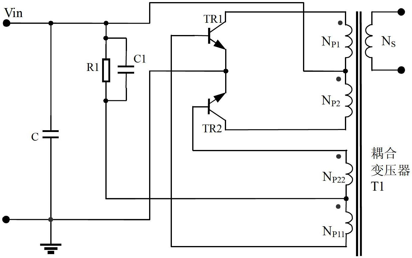
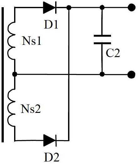
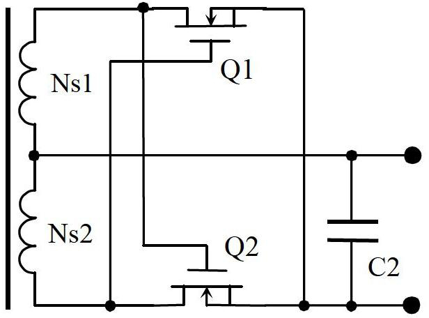
[0041] The circuit of the first embodiment of the present invention is as Figure 4 As shown, the circuit is a self-excited push-pull converter based on the Royer circuit, including a transformer and a synchronous rectification output circuit. The output section of the transformer includes the power output winding and the synchronous winding. The output winding consists of two separate windings, in which a pair of opposite ends are connected and drawn out as the positive output terminal of the power supply. The other pair of opposite ends of the output winding are respectively connected to the drains of the two synchronous rectification MOS transistors. The sources of the two synchronous rectification MOS transistors are connected and drawn out as the negative pole of the output terminal of the power supply. A filter capacitor is connected between the positive pole and the negative pole of the output terminal of the power supply. The synchronous winding also includes two se...

Embodiment 2

[0058] The circuit of the second embodiment of the present invention is as Figure 4 As shown, the schematic diagram of the transformer winding is shown in Figure 10 shown. The transformer is divided into two parts, the first part with a smaller cross-sectional area and the second part with a larger cross-sectional area. The magnetic core material of both parts is the same. Transformer lead numbers correspond to Figure 4 The circuit number of the transformer shown in the circuit, the terminal with the same name is determined according to the circuit identification. The difference from Embodiment 1 is that the first part of the transformer is divided into two sections with the same magnetic circuit length and cross-sectional area, and there is a spacer core between the two sections, and the spacer core also belongs to the composition of the second part of the magnetic core. The two windings coupling the synchronous rectification synchronous signal are independently wound ...

Embodiment 3

[0060] The circuit diagram of the third embodiment of the present invention is as Figure 11 As shown, the schematic diagram of the transformer winding is shown in Figure 5 or Figure 10 shown. As a further improvement of Embodiment 1 and Embodiment 2, it is characterized in that in the two MOS transistors of the output synchronous rectification circuit, a resistor is connected in parallel to the gate and source of each MOS transistor.

[0061] The third embodiment realizes the synchronous rectification of the Royer circuit and improves the conversion efficiency, which is the same as the working principle of the content of the invention and the working principle of the first embodiment. According to the realization principle of the present invention, when the first part of the transformer core is saturated, the induced voltage of the synchronous rectification driving winding coupled to the first part of the transformer core will rapidly decrease and turn off the synchronous...


PUM


Abstract

The invention discloses a method for improving the working efficiency of a self-excited push-pull converter and the self-excited push-pull converter. The method comprises the steps of setting an output circuit of the converter as a synchronous rectification output circuit, and turning off a synchronizing signal of the synchronous rectification before overturning of a working state of the converter. The self-excited push-pull converter for realizing the method comprises a transformer and a synchronous rectification output circuit, wherein the synchronous rectification output circuit is connected to an output winding of the transformer, the synchronous rectification output circuit comprises two synchronous rectification metal oxide semiconductor (MOS) tubes, and the turnoff of the synchronizing signal of the synchronous rectification is ahead of the overturning of the working state of the converter. Due to the adoption of the method and the self-excited push-pull converter, the problem that the circuit cannot be overturned normally when the synchronous rectification circuit is applied to a Royer circuit can be solved; and the synchronous rectification circuit can be normally applied to the Royer circuit, the working efficiency of the Royer circuit is further improved, and especially the working efficiency of the Royer circuit in the low-voltage output application field can be improved.

Description

technical field [0001] The invention relates to a method for improving the working efficiency of a self-excited push-pull converter based on a Royer circuit, and also relates to a self-excited push-pull converter for realizing the method. Background technique [0002] The existing self-excited push-pull converter, the circuit structure comes from the self-excited oscillating push-pull transistor single-transformer DC converter invented by G.H.Royer in 1955, also known as the Royer circuit, which is also a high-frequency conversion control circuit the beginning. Part of the circuit comes from the self-excited push-pull double transformer circuit invented by Jen Sen in the United States in 1957, which was later called the self-oscillating Jensen circuit or Jensen circuit. These two circuits are collectively referred to as self-excited push-pull converters. The relevant working principle of the self-excited push-pull converter is described on pages 67 to 70 of "The Principle ...

Claims


Application Information

Patent Timeline
IPC IPC(8): H02M3/337
CPCY02B70/1475Y02B70/10
Inventor 贾宇锋蔡家添
Owner MORNSUN GUANGZHOU SCI & TECH
Why Eureka
Try Eureka