Solar LED lighting driving circuit

A technology of LED lighting and driving circuit, which is applied in the direction of lighting devices, lamp circuit layout, electric light source, etc., which can solve the problems of low overall lifespan and achieve the effects of low manufacturing cost, low heat generation, and improved efficiency

Inactive Publication Date: 2012-09-19
SUIZHONG ZHONGWEI TECH
View PDF0 Cites 2 Cited by
  • Summary
  • Abstract
  • Description
  • Claims
  • Application Information

AI Technical Summary

Problems solved by technology

[0004] In order to solve the problem that the overall service life is too low due to the existence of capacitance in the driving voltage

Method used


Image

  • Solar LED lighting driving circuit
  • Solar LED lighting driving circuit

Examples


Embodiment Construction

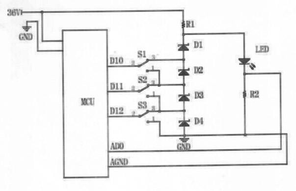
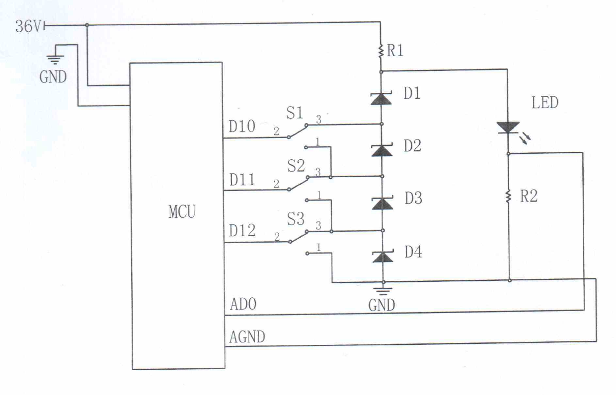
[0011] As shown in the figure, the positive 36V DC is connected to the microcontroller MCU, and the microcontroller is provided with DI0, DI1, DI2 output terminals and ADO, AGND return terminals. DI0 passes through the electronic switch S1 and the anode of the voltage regulator tube D1 and The cathode of D2 is connected, DI1 is connected with the anode of the voltage regulator D2 and the cathode of D3 through the electronic switch S2, and DI2 is connected with the anode of the voltage regulator D3 and the cathode of D4 through the electronic switch S3; the positive 36V DC passes through the current limiting resistor R1 is connected with LDE, the LED is connected with AD0 through the current limiting resistor R2, and grounded, and AGND is connected with the anode of the Zener diode D4 and the ground terminal GND, forming the circuit of the present invention.

[0012] Working process of the present invention:

[0013] The +36V powered by the solar battery is connected to one end...


PUM

PropertyMeasurementUnit
Resistanceaaaaaaaaaa

Abstract

The invention relates to a solar LED (light-emitting diode) lighting driving circuit. Positive 36V direct current power is accessed into a micro-controller unit (MCU) and connected with a voltage-stabilizing tube via an electronic switch; and the positive 36V direct current power is connected with an LED through a current-limiting resistor R1, and the LED is grounded through a current-limiting resistor R2. According to the solar LED lighting driving circuit disclosed by the invention, on the premise of not requiring an inductor and a capacitor, the step-up and step-down voltage transformation property can be achieved, and the solar LED lighting driving circuit has the advantages of high efficiency, simple structure, low manufacturing cost, low calorific value, easiness in maintenance and long service life, and is suitable for being used on circuits of solar LED lighting devices.

Description

technical field [0001] The invention relates to a circuit in the technical field of voltage conversion, in particular to a solar LED lighting driving circuit. Background technique [0002] In the power supply system of solar battery lighting, the voltage up and down conversion is used to drive LED white light lighting. Generally, Buck, Boost, Buck-Boost and other up and down circuits are used, but these circuits require inductors and capacitors. . [0003] However, a large amount of heat is emitted during the LED white light lighting process. The capacitor is affected by the temperature, and its life is proportionally reduced. Generally, it will be damaged after more than 1,000 hours, and the maximum is more than 10,000 hours. The present invention aims to eliminate the buck-boost circuit. The inductance and capacitance in the LED drive circuit enable a longer overall lifespan. Contents of the invention [0004] In order to solve the problem that the overall lifespan is ...

Claims


Application Information

Patent Timeline
IPC IPC(8): H05B37/02
Inventor 毕建莹
Owner SUIZHONG ZHONGWEI TECH
Why Eureka
Try Eureka