Method and device for energy harvesting

一种能量、采集模块的技术,应用在能量采集和装置领域,能够解决振动易损坏等问题,达到制造简单、容易成本效率的效果

Active Publication Date: 2012-09-19
MURATA MFG CO LTD
View PDF8 Cites 9 Cited by
  • Summary
  • Abstract
  • Description
  • Claims
  • Application Information

AI Technical Summary

Problems solved by technology

and many known harvesters are vulnerable to vibrations beyond the limits of intended use

Method used


Image

  • Method and device for energy harvesting
  • Method and device for energy harvesting
  • Method and device for energy harvesting

Examples


Embodiment Construction

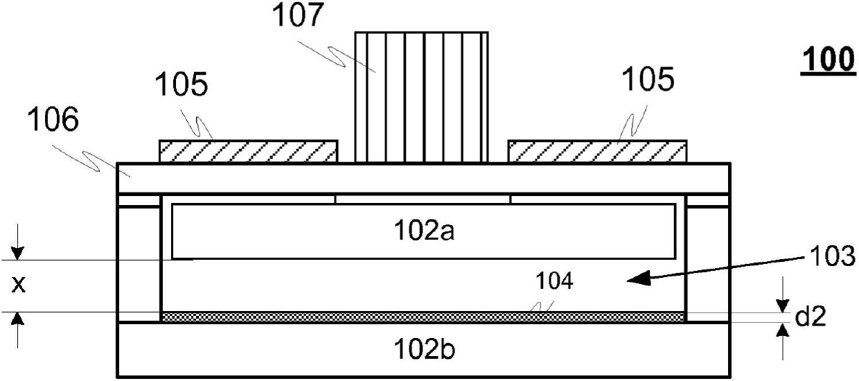
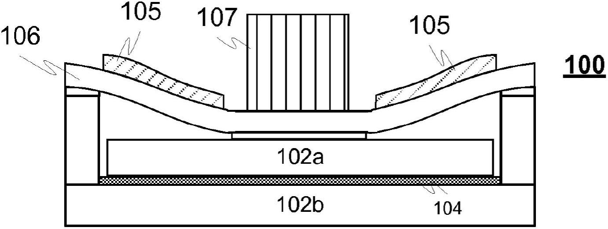
[0027] Figure 1A-1B An exemplary device 100 for harvesting energy from vibration, strain, rotation and / or impact is illustrated in accordance with an advantageous embodiment of the present invention, wherein at Figure 1A-1B The principle of operation of the device 100 is also shown in , where the device is in the open position and in Figure 1Bin the closed position.

[0028] The device 100 advantageously comprises a capacitor harvesting module comprising two capacitor plates 102a, 102b arranged substantially parallel to each other such that at least one of said plates 102a is suitable for Instead it moves in a direction substantially perpendicular to the other capacitor plate 102b and thus forms a variable gap 103 between said plates. As the distance changes, so does the capacitance between the plates 102a, 102b, and thus also electrical power is generated to the power output. For example, when the device 100 is used in a wheel, the capacitor is turned off and on with ever...


PUM


Abstract

A device (100) harvests energy from vibration and / or strain and utilises both capacitive (102a, 102b) and piezoelectric elements(105). The principle of operation is out-of-plane capacitive harvester,where the bias voltage for the capacitive element is generated with a piezoelectric element(105). The device utilizes a thin dielectric film (104) between the capacitor plates (102a, 102b) maximizing the harvested energy and enabling the harvester operation in semi-contact mode so that short circuits are prevented. For example when utilised in a wheel or the like, the capacitor is closed and opened at every strike or every turn of a wheel being thus independent of the harvester's mechanical resonance frequency.

Description

technical field [0001] The present invention relates to devices and methods for harvesting energy from vibration, strain, rotation and / or impact. Background technique [0002] Over the past few decades, the need to power eg wireless sensors has driven research activity on energy harvesting from the environment. The wireless communication capability cannot be fully utilized if power is provided through wires, or if batteries have limited operating time, bulky size, and heavy weight. [0003] The energy harvesting mechanism depends on the environment and application. Various energy sources have been proposed: light, heat (thermal gradients), strain, vibrations, electromagnetic fields, dynamics, air flow, pressure changes and radioactive materials, and also vibrations. [0004] One of the many investigated applications for energy harvesting is eg the automotive tire pressure monitoring system TPMS. Battery operated devices already exist on the market, but the harvester will ...

Claims


Application Information

Patent Timeline
Patent Type & Authority Applications(China)
IPC IPC(8): B81B3/00H01L41/113B60C23/04
CPCB60C23/0411H02N2/186Y10T29/42H10N30/304B81B3/0021H02N1/08H10N30/30B81B3/00B60C23/04
Inventor 安娜-马伊加·卡尔凯内恩尤卡·屈内雷宁雷夫·罗斯基尔海基·凯斯玛
Owner MURATA MFG CO LTD
Why Eureka
Try Eureka