
Automatic forming equipment of pointed cone part of spiral ground pile

A technology of automatic forming and spiral ground piles, which is applied in the direction of forming tools, metal processing equipment, manufacturing tools, etc., can solve the problems that the splicing surfaces cannot be fully fitted, the solid cone tip cannot be formed, and the force cannot be applied, etc. Long life, high processing efficiency, and easy replacement

Inactive Publication Date: 2012-09-26
浙江博雷重型机床制造有限公司
View PDF10 Cites 2 Cited by
  • Summary
  • Abstract
  • Description
  • Claims
  • Application Information

AI Technical Summary

Problems solved by technology

However, the mold is composed of upper and lower mold blocks, because the two mold blocks are in surface contact, and some conical grooves are formed on the joint surface. The existing technology cannot guarantee the full fit of the joint surface, so the two Part of the conical groove on the die block cannot be closed into a complete conical tip, and the force cannot be applied to the tube tip, so that the steel pipe can only be processed into a conical tube, and a solid conical tip cannot be formed at the end of the tube

Method used


Image

  • Automatic forming equipment of pointed cone part of spiral ground pile
  • Automatic forming equipment of pointed cone part of spiral ground pile
  • Automatic forming equipment of pointed cone part of spiral ground pile

Examples


Embodiment 1

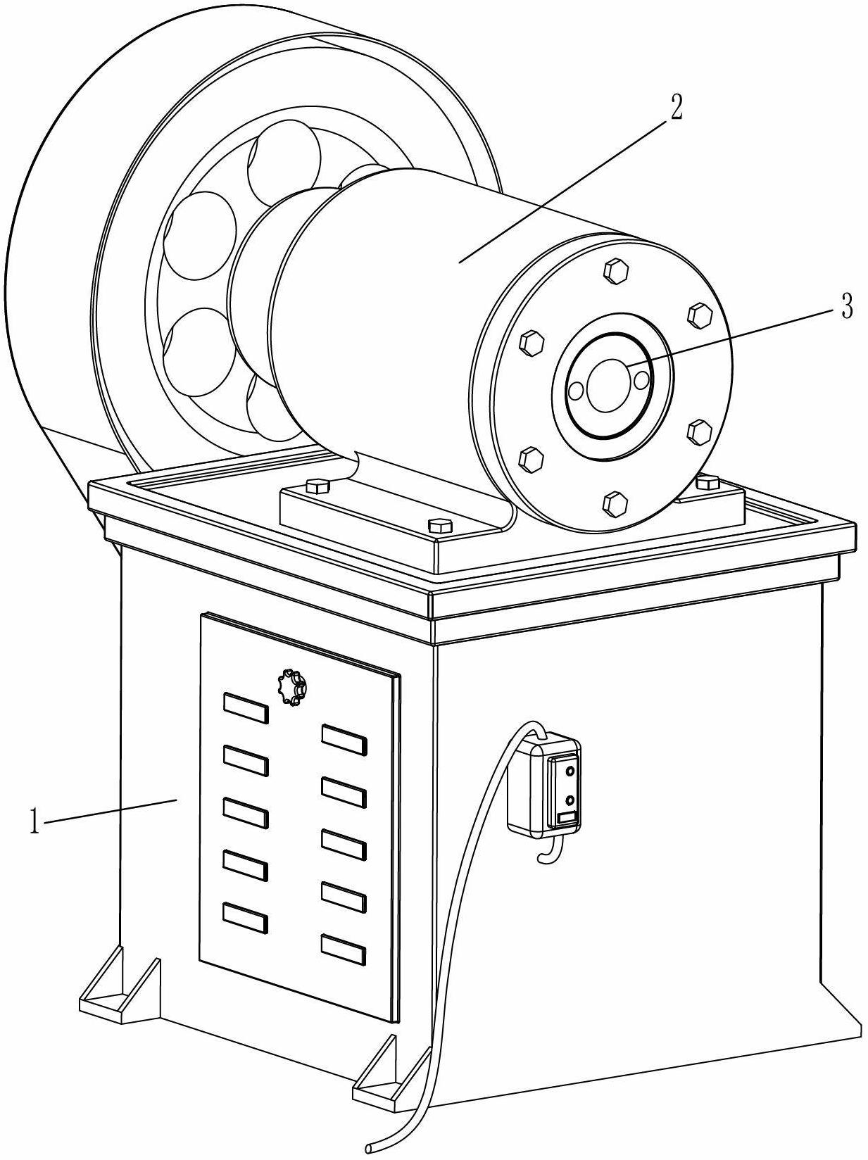
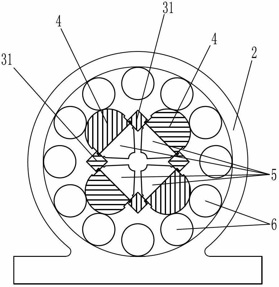
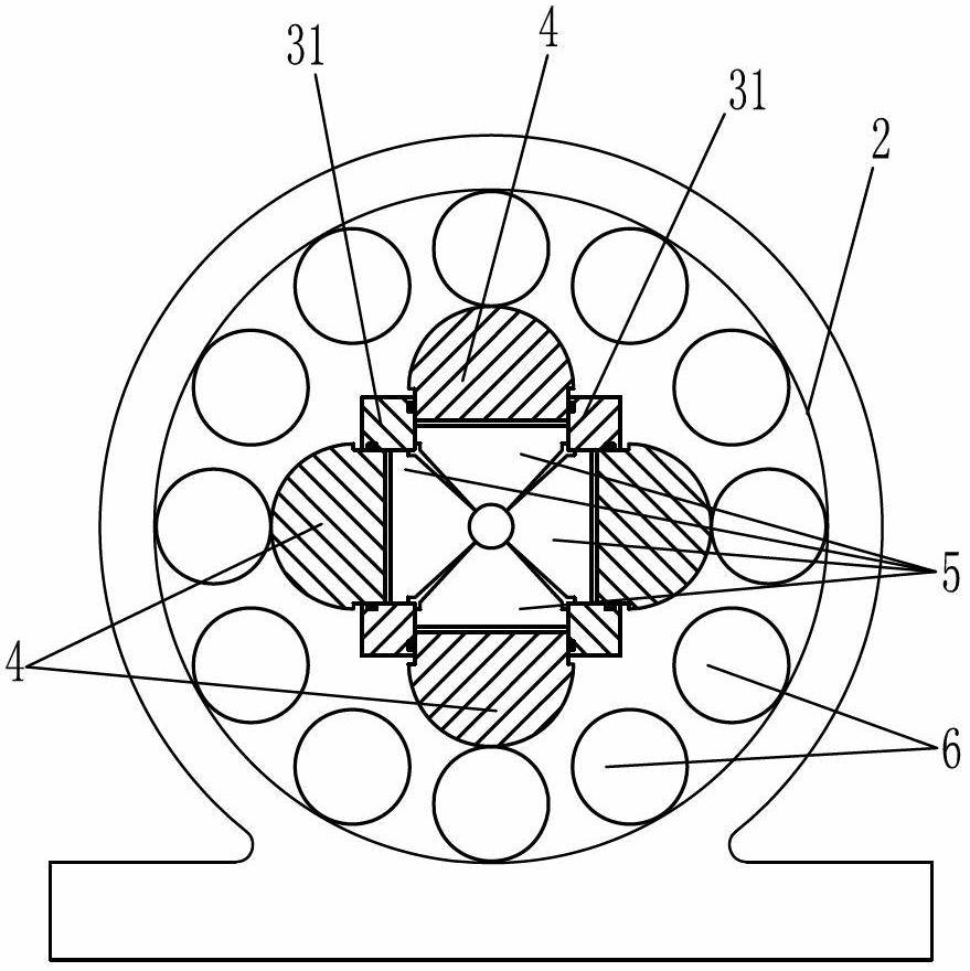
[0027] An automatic forming device for the cone of a spiral ground pile, comprising a plurality of conical tube machines distributed side by side, a frame is arranged on the feeding side of the multiple conical tube machines, and a plurality of feeding manipulators, a A feeding device and a discharging device, the plurality of feeding manipulators and the plurality of tapered tube machines are arranged in one-to-one correspondence. Wherein, the cone pipe machine such as figure 1 , figure 2 , image 3 As shown, it includes a machine base 1, a housing 2 on the machine base 1, a main shaft 3 driven by a motor through a pulley, a mold 5 and a hammer 4 are installed in the mold cavity of the main shaft 3, and between the hammer 4 and the housing 2 Roller group 6 is arranged between, described hammerhead 4 comprises four hammerhead blocks, and described mold 5 is made up of four petal mold blocks with the same structure, and the splicing part of each petal mold block is triangula...


PUM


Abstract

The invention discloses automatic forming equipment of a pointed cone part of a spiral ground pile. The automatic forming equipment comprises a conical pipe forming machine, a feeding manipulator, a feeding device and a discharging device, wherein the feeding device comprises a quantitative feeding device. The conical pipe forming machine comprises a base, a shell and a main shaft, wherein a die cavity of the main shaft is internally provided with a die and a hammerhead, a rolling shaft group is arranged between the hammerhead and the shell, the hammerhead comprises a plurality of hammerhead blocks, the die is formed by splicing at least three segments of die blocks, the splicing part between every two adjacent segments of die blocks is triangular, one side of the top end of the splicing part is provided with a partial conical-surface groove, a gap is remained between two side walls of the splicing part between every two adjacent segments of die blocks and closed at the splicing center of the plurality of segments of die blocks, the partial conical-surface grooves on the plurality of segments of die blocks are spliced to form an integral conical hole, and the plurality of segments of die blocks respectively correspond to the hammerhead blocks one to one. By adopting the technical scheme, the problem that a solid cone point cannot be formed in the cone forming process of a large-pipe-diameter steel pipe in the prior art is solved.

Description

technical field [0001] The invention belongs to the field of processing equipment for spiral ground piles, and in particular relates to automatic forming equipment for the tip cone of spiral ground piles. Background technique [0002] The patent document with the publication number CN102490265A discloses a spiral extrusion production line for the taper part of the pile tip, which includes a plurality of conical tube machines distributed side by side. A frame is arranged on the feed side of the multiple conical tube machines. The frame is provided with a plurality of feeding manipulators, a feeding device and a discharging device; the plurality of feeding manipulators are set in one-to-one correspondence with the plurality of tapered tube machines, and the feeding manipulators include The base is horizontally slidably connected with a sliding seat, the sliding seat is driven and slid by the driving mechanism and its sliding direction is consistent with the feed and retreat di...

Claims


Application Information

Patent Timeline
Patent Type & Authority Applications(China)
IPC IPC(8): B21D31/06B21D37/10
Inventor 高尔荣谭广沈平
Owner 浙江博雷重型机床制造有限公司
Learn More