
Tool for sheet metal working machine and method for cutting film

A metal plate and processing machine technology, applied in metal processing and other directions, can solve the problem of inability to process small radius curves and contours, and achieve the effect of small wear

Active Publication Date: 2016-01-20
TRUMPF WERKZEUGMASCHINEN GMBH & CO KG
View PDF7 Cites 0 Cited by
  • Summary
  • Abstract
  • Description
  • Claims
  • Application Information

AI Technical Summary

Problems solved by technology

The problem here is that it may not be possible to machine curved profiles with small radii

Method used


Image

  • Tool for sheet metal working machine and method for cutting film
  • Tool for sheet metal working machine and method for cutting film
  • Tool for sheet metal working machine and method for cutting film

Examples


Embodiment Construction

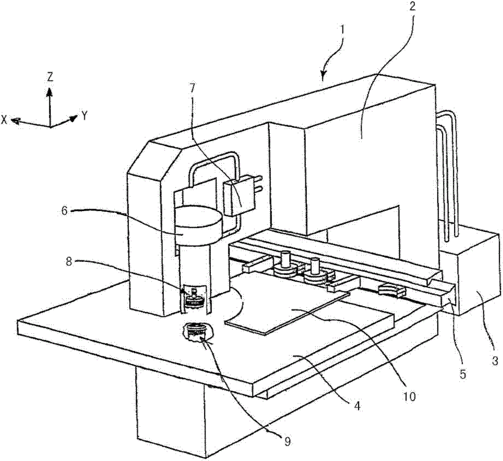
[0012] figure 1 A punching machine 1 is shown according to one embodiment as a sheet metal working machine. However, laser processing machines such as laser cutting machines or laser welding machines or combined stamping / laser cutting machines are also possible, for example.

[0013] The press machine 1 includes a C-shaped frame 2 as a main member. The C-frame 2 consists of a torsionally rigid welded structure made of steel. At the rear end of the C-shaped frame 2 is arranged a hydraulic power unit 3 as a power source for the punching movement.

[0014] Furthermore, the punching machine 1 comprises mechanical control means (not shown) connected to all actuators of the punching machine 1 and controlling said actuators.

[0015] A workpiece supporting device 4 in the form of a processing table for placing workpieces is provided on the inner side of the lower part of the C-shaped frame 2 . Here, the workpiece is a sheet metal panel 10 .

[0016] Also provided on the processi...


PUM


Abstract

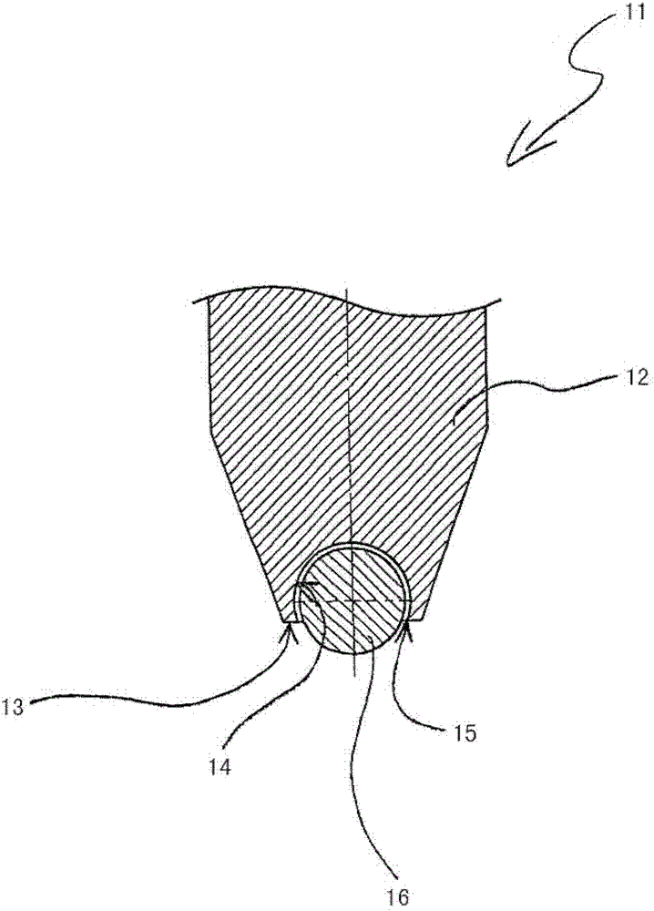
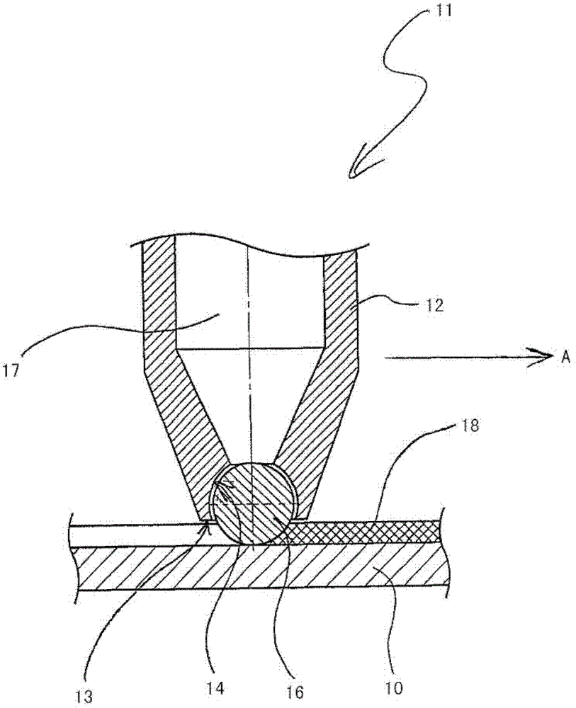
The tool (11) has a rotatably supported ball (16) designed such that a film (18) is separated from a metal sheet (10) by rolling movement of the ball. A ball retaining device (12) has a retaining area (14) at an end that is turned towards the sheet metal, where diameter of the ball is less than 1 mm. The retaining device has a hollow cavity (17) for accommodating lubricant for reducing friction coefficients between a surface of the ball and an inner surface of the retaining area. The hollow cavity is connected with the retaining area, where the ball is made from ceramics. An independent claim is also included for a method for separating a film from sheet metal.

Description

technical field [0001] The present invention relates to a tool for a sheet metal working machine and a method for cutting a film, in particular, the present invention relates to a tool for a sheet metal working machine and a tool for cutting The film on the board to prevent it from scratching. Background technique [0002] Known tools for cutting protective films on metal panels include scribes. The scribe has a 90 degree tip cone angle and is spring loaded to cut through the film without damaging the surface of the sheet metal. By using compression springs with different pressures, the necessary pressure can be varied. However, the resistance to the tool increases when the surface structure of the sheet metal is slightly uneven or varies in thickness. Therefore, it is easy to generate scratches or marks on the surface of the metal sheet, especially when the processing direction is inclined to the polishing direction of the brushed metal sheet. [0003] Tools with spring...

Claims


Application Information

Patent Timeline
Patent Type & Authority Patents(China)
IPC IPC(8): B26D1/00B26D5/08B26D7/26B21D22/02
CPCB26F3/04B26D3/085B26F1/3813C23F1/08Y10T83/04Y10T83/263Y10T83/6656Y10T83/9372
Inventor O·施泰因格鲁贝尔H·卡钦纳
Owner TRUMPF WERKZEUGMASCHINEN GMBH & CO KG
Learn More