Ultralow-speed flow box device

A headbox, ultra-low speed technology, applied in textile and paper making, paper machine, wet end of paper machine, etc., can solve the problems of low spraying speed, high cost, unable to meet the requirements of the liquid level of the homogenizing roll, etc. Achieve the effect of reducing equipment cost, simple and easy technical means, positive technical effect and promotion and application value

Inactive Publication Date: 2012-09-26
SOUTH CHINA UNIV OF TECH
View PDF8 Cites 8 Cited by
  • Summary
  • Abstract
  • Description
  • Claims
  • Application Information

AI Technical Summary

Problems solved by technology

[0006] Obviously, when the speed of the paper machine is very low, the headbox must have a very low spraying speed to meet the requirements of the pulp-net speed ratio. When the spraying speed is lower than 70m / min, the headbox in the weir pool The height of the liquid level is less than 100mm, and the diameter of the general homogenizing roller is not less than 100mm. Obviously, the general open flow flow cannot meet the requirements of the homogenizing roller for the liquid level. The existing technology is to use the vacuum method, that is, P <0, so that the liquid level of the headbox can be increased to meet the requirements of the homogenizing roller
[0007] However, the vacuum headbox needs to be equipped with a vacuum system, exhaust pipeline and corresponding control system, which is obviously more expensive than an open headbox. At the same time, when the speed of the paper machine changes little, the change of the required vacuum degree is also small. There are very high requirements for the accuracy of the control system

Method used


Image

  • Ultralow-speed flow box device
  • Ultralow-speed flow box device
  • Ultralow-speed flow box device

Examples


Embodiment

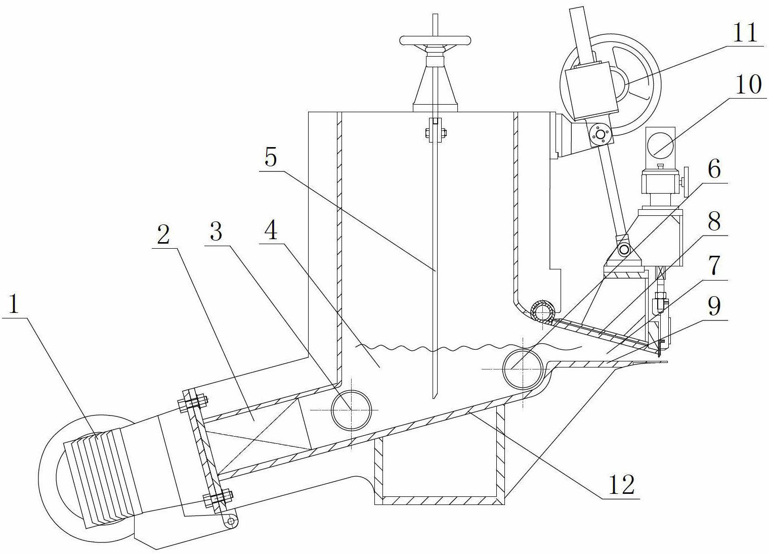
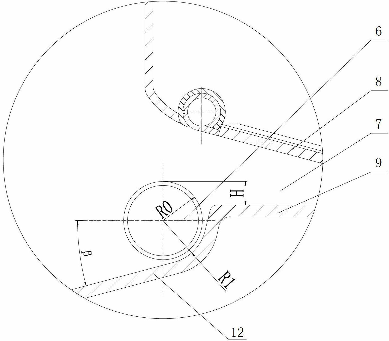
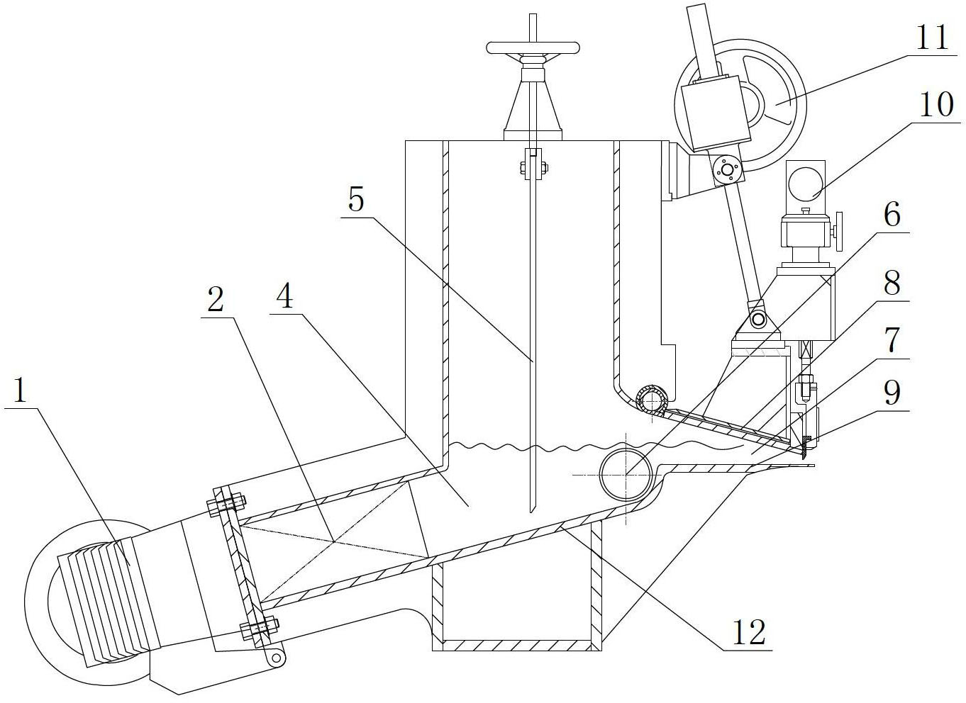
[0023] Such as figure 1 As shown, the ultra-low-speed headbox device of the present invention includes a stock inlet main pipe 1, a stock distribution element 2, an energy-dissipating homogenizer roller 3, a weir pool 4, a flashboard 5, a rectifier homogenizer roller 6, a lip area 7, an upper lip Plate 8, lower lip 9, fine-tuning device 10, upper lip lifting device 11, headbox bottom 12; the inner bottom of the headbox bottom 12 is inclined upward to the lower lip 9 and transitions with the lower lip 9 in an arc Connected, the rectifying and homogenizing roller 6 is installed at the arc transition, and the energy-dissipating homogenizing roller 3 is arranged at the outlet of the pulp distribution element 2 .

[0024] Such as image 3 As shown, the slurry inlet main pipe 1 is a square cone main pipe or a conical main pipe, and the slurry distribution element 2 is one of an orifice plate, a stepped diffuser or a tube bundle. Because the slurry coming out of the stepped diffuse...


PUM


Abstract

The invention discloses an ultralow-speed flow box device comprising a pulp inlet main pipe, a pulp distributing element, a flow box bottom plate, an upper lip plate, a lower lip plate and a rectifier roll. In the flowing direction of pulp, the interior bottom surface of the flow box bottom plate is inclined upwards to the lower lip plate and is in arc transition connection with the lower lip plate, and the rectifier roll is mounted in the arc transition position. Therefore, the height of the rectifier roll can be reduced, and the process requirement on submersion of the rectifier roll is met when the speed of a paper machine is very low and the liquid level above the lower lip plate in the flow box is lower. Through the adoption of the structure, the flow box can meet the requirement on ultralow-speed papermaking of the paper machine under an open condition, and is not needed to be equipped with a vacuum system and a control system so as to reduce equipment cost. The invention has the advantages that the technical measure is simple, convenient and feasible, and positive technical effects and popularization and application values are achieved.

Description

technical field [0001] The invention relates to the technical field of pulping and papermaking, in particular to an ultra-low-speed headbox device. Background technique [0002] The homogenizing roller is the most commonly used energy dissipation and rectifying element in the headbox of medium and low speed paper machines. Flow, disperse the role of fiber flocculation. However, the homogenizing roller must be immersed in the slurry in the headbox during the application process, otherwise, if the homogenizing roller is exposed to the slurry surface, air will be brought in due to the rotation of the homogenizing roller, resulting in air bubbles, and it is also easy to sag. [0003] According to the requirements of the pulp-wire speed ratio, a certain paper machine wire speed must have a corresponding headbox spray speed, and the headbox spray speed is determined by the following formula: [0004] V 1 = KV ...

Claims


Application Information

Patent Timeline
Patent Type & Authority Applications(China)
IPC IPC(8): D21F1/02D21F1/06
Inventor 刘建安张成樊慧明陈克复
Owner SOUTH CHINA UNIV OF TECH
Why Eureka
Try Eureka