Visual narrow rectangular channel aerosol motion deposition system

A rectangular channel and deposition system technology, applied in the field of multiphase flow, can solve the problems of design and processing difficulties, inability to measure the velocity field and concentration field in real time online, and inability to observe the continuous motion of aerosol particles online, and achieve detailed observation and measurement. , the effect of real-time observation and measurement

Inactive Publication Date: 2012-09-26
NORTH CHINA ELECTRIC POWER UNIV (BAODING)
View PDF2 Cites 16 Cited by
  • Summary
  • Abstract
  • Description
  • Claims
  • Application Information

AI Technical Summary

Problems solved by technology

At present, many fine particle dynamic models have been established at home and abroad, all of which simulate and approximate the real process from different angles. Each model has different application conditions and emphases; under different specific conditions, the movement of fine particles and The deposition mechanism is also different. The removal efficiency of fine particle removal devices based on the principles of sedimentation and aggregation is not high for submicron and nanometer particles; in terms of aerosol observation technology, advanced PDA systems are mostly used , but the measurement process is complicated, and it is necessary to find a suitable measurement method according to the actual situation
[0004] Due to the difficulty of design and processing, the current observation of aerosol particles in the channel mostly adopts the method of measuring the concentration difference between the front and rear ends without windows, and it is impossible to observe the overall change of the entire flow field.
In this way, the continuous movement of aerosol particles cannot be observed online, especially the velocity field, concentration field, etc. of all areas in the channel cannot be measured online in real time, so it has great limitations

Method used


Image

  • Visual narrow rectangular channel aerosol motion deposition system
  • Visual narrow rectangular channel aerosol motion deposition system
  • Visual narrow rectangular channel aerosol motion deposition system

Examples


Embodiment Construction

[0025] The present invention will be further described below in conjunction with the accompanying drawings and specific embodiments.

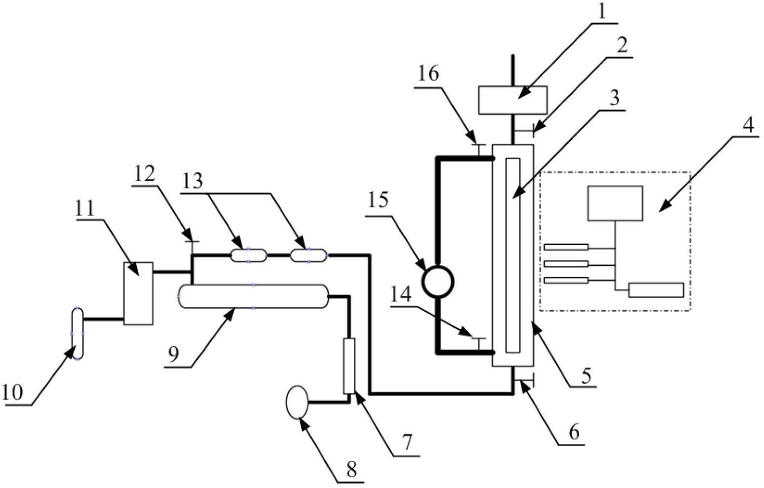
[0026] Such as figure 1 As shown, this system includes: an exhaust gas purification device 1, a thermocouple 2 at the outlet end of the visible section, a thermocouple 6 at the inlet end of the visible section 5, and a thermocouple 6 at the inlet end of the visible section are connected in sequence, and the visible section 5 is equipped with a quartz glass window 3, and the aerosol The observation equipment 4 is opposite to the quartz glass window 3, the rotameter 7 is connected to the fan 8 and the heater 9 respectively, the heater 9 is connected to the aerosol generator 11 and the thermocouple 12 at the outlet end of the heater respectively, and the aerosol generator 11 is connected to the thermocouple 12 at the outlet end of the heater. The gas cylinder 10 is connected, the thermocouple 12 at the outlet end of the heater is connected with th...


PUM

PropertyMeasurementUnit
lengthaaaaaaaaaa
widthaaaaaaaaaa
thicknessaaaaaaaaaa

Abstract

The invention discloses a visual narrow rectangular channel aerosol motion deposition system which belongs to the technical field of multiphase flow. In the system, mainstream gas is supplied by a fan and is heated by a heater; an aerosol generator is added with small solid particles or liquid droplets by a branch circuit to form a disperse system; the disperse system is cooled when passing through a visual section and is finally discharged by a tail gas purifying device; and the observation and measurement on fine particles are implemented by utilizing aerosol observing equipment through the visual section. The system is mainly characterized in that the visual section is provided with a quartz glass window with the length of 1,000mm, so that the observation and the measurement on the integral section of continuous motion of the fine particles are implemented; and the system is safe and reliable and various parameters such as the temperature, the flow, the concentration and the like can be regulated. The system is beneficial to research on the aspects of subjects of a total mechanical equipment structure, the multiphase flow, the environment protection, the aerosol motion, the thermophoresis effect and the like.

Description

technical field [0001] The invention belongs to the technical field of multiphase flow, and in particular relates to a visible narrow rectangular channel aerosol motion deposition system. Background technique [0002] Aerosol is a colloidal dispersion system in which solid or liquid small particles are dispersed and suspended in a gas medium, and the equivalent diameter of the small particles as the dispersed phase is about 10 -5 m~10 -9 m. Smoke, fog, haze, and flying dust are all specific forms of aerosols. In industrial production, the study of aerosol behavior characteristics is of great significance. The flue gas emitted by various boilers and engines pollutes the environment; the wear of the heat transfer tube in the steam generator of the nuclear power water reactor, the deposition of graphite dust in the pipe in the high temperature gas-cooled reactor, and the serious accident of the nuclear power plant will produce a large amount of radioactive aerosols. In ter...

Claims


Application Information

Patent Timeline
Patent Type & Authority Applications(China)
IPC IPC(8): G01N15/04
Inventor 周涛王泽雷樊昱楠汝小龙
Owner NORTH CHINA ELECTRIC POWER UNIV (BAODING)
Why Eureka
Try Eureka