
Display panel drive device, semiconductor integrated device, and image data acquisition method

A display panel and driving device technology, applied to static indicators, instruments, etc., can solve problems such as large noise

Active Publication Date: 2012-09-26
LAPIS SEMICON CO LTD
View PDF6 Cites 4 Cited by
  • Summary
  • Abstract
  • Description
  • Claims
  • Application Information

AI Technical Summary

Problems solved by technology

[0004] Thus, when the value of each display data introduced into the second latch group is switched from a low level state to a high level state or from a high level state to a low level state, a momentary large current flows into the signal line, as a result, a large noise occurs in the

Method used


Image

  • Display panel drive device, semiconductor integrated device, and image data acquisition method
  • Display panel drive device, semiconductor integrated device, and image data acquisition method
  • Display panel drive device, semiconductor integrated device, and image data acquisition method

Examples


Embodiment

[0039] figure 1 It is a diagram showing a schematic configuration of a liquid crystal display device equipped with a drive device for a display panel according to the present invention.

[0040] exist figure 1 Among them, in the display panel 20 as a liquid crystal panel, in order to drive the liquid crystal layer (not shown), n scanning lines S respectively extending in the horizontal direction of the 2D screen are provided. 1 ~Sn and m data lines D elongated in the vertical direction of the 2D screen respectively 1 ~D m . Furthermore, display units serving as pixels are formed in regions where the scanning lines and the data lines intersect each other.

[0041] The drive control unit 10 generates a signal for each scanning line S based on the input video signal. 1 ~S n Scan control signals of scan pulses are sequentially applied and supplied to the scan driver 11 .

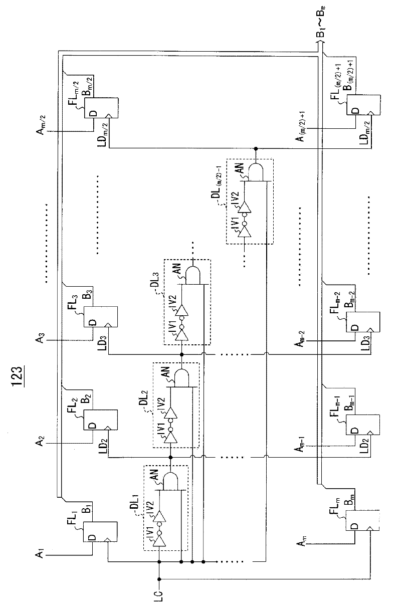
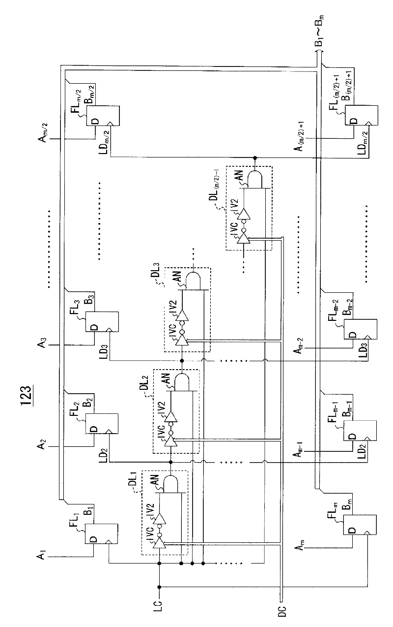
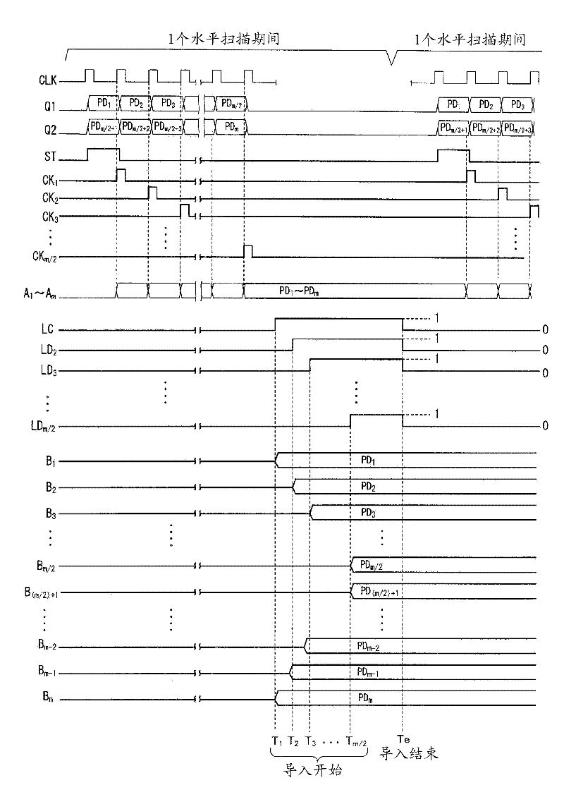
[0042] In addition, the drive control unit 10 such as figure 2 As shown, a lead-in start pulse sig...


PUM


Abstract

A display panel drive device for applying a drive pulse to data lines of a display panel according to a video signal includes a latch portion and an output amplifier. The latch portion includes a first latch section, a delay circuit, and a second latch section. The first latch section is provided for capturing the pixel data pieces or retaining the pixel data pieces. The delay circuit is provided for generating a delayed load clock signal. The second latch section is provided for capturing the pixel data pieces or retaining the pixel data pieces. The delayed load clock signal is transited to the first level state after a first delay time, and the delayed load clock signal is transited to the second level state after a second delay time shorter than the first delay time.

Description

technical field [0001] The present invention relates to a driving device for driving a display panel, and in particular to a driving device for applying a driving pulse corresponding to an input video signal to each data line of the display panel, a semiconductor integrated device having the driving device, and a pixel data of the display panel driving device. import method. Background technique [0002] In a flat display panel such as a liquid crystal display panel, n (n is an integer greater than or equal to 2) scanning lines elongated in the horizontal direction of the 2D screen are arranged in an intersecting manner, and in the vertical direction of the 2D screen m (m is an integer greater than or equal to 2) signal lines extending in one direction. Electrodes serving as pixels are formed at intersections of these signal lines and scanning lines. Also, a signal driver is mounted on the liquid crystal display panel to apply a voltage corresponding to a luminance level i...

Claims


Application Information

Patent Timeline
Patent Type & Authority Applications(China)
IPC IPC(8): G09G3/20G09G3/36
CPCG09G3/3685G09G2310/027G09G2310/0286G09G2310/0291G09G3/20G09G3/36
Inventor 石井宏明平间厚志
Owner LAPIS SEMICON CO LTD
Learn More