LC (inductance/capacitance) resonance drive circuit for ultrasonic motor and control method of LC resonance drive circuit

A technology of ultrasonic motor and driving circuit, which is applied in the direction of generator/motor, piezoelectric effect/electrostrictive or magnetostrictive motor, electrical components, etc., and can solve the problems of poor driving control method and other problems

Inactive Publication Date: 2012-09-26
HENAN UNIV OF SCI & TECH
View PDF4 Cites 13 Cited by
  • Summary
  • Abstract
  • Description
  • Claims
  • Application Information

AI Technical Summary

Problems solved by technology

[0007] The purpose of the present invention is to provide a kind of LC resonant drive circuit and its control m...

Method used


Image

  • LC (inductance/capacitance) resonance drive circuit for ultrasonic motor and control method of LC resonance drive circuit
  • LC (inductance/capacitance) resonance drive circuit for ultrasonic motor and control method of LC resonance drive circuit
  • LC (inductance/capacitance) resonance drive circuit for ultrasonic motor and control method of LC resonance drive circuit

Examples


Embodiment Construction

[0018] The present invention will be described in further detail below in conjunction with the accompanying drawings.

[0019] Resonant Circuit Embodiment

[0020] The AC sides of the A and B two-phase bridge drive circuits that drive the ultrasonic motor are all provided with series matching inductors L, and the A and B two-phase bridge drive circuits are respectively provided with DC bus voltages for adjusting the corresponding phase bridge drive circuits. The Boost voltage boosting circuit is characterized in that the power switch tube Q of the Boost voltage boosting circuit is connected in series with a diode D1, and the anode of the diode D1 is connected to the series connection point of the series matching inductor L and the capacitor C.

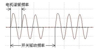
[0021] The ultrasonic motor (USM) can be considered capacitive near the resonant frequency, which is equivalent to a capacitor C. The Boost step-up LC resonant driving circuit of the present invention is as figure 1 shown. Since the...


PUM


Abstract

The invention relates to an LC (inductance/capacitance) resonance drive circuit for ultrasonic motor and a control method of the LC resonance drive circuit. According to the capacitance load characteristic of the ultrasonic motor, inductors are serially connected and matched to form a transformer-free drive circuit with an ultrasonic motor body and LC resonance boosting. Furthermore, the invention provides a method for fixing all circuit parameters and changing a drive signal frequency, a duty ratio and a resonance cycle only, and thus the drive control of the ultrasonic motor is realized. By adopting the USR30 ultrasonic motor, experimental verification is carried out.

Description

technical field [0001] The invention relates to an ultrasonic motor, in particular to the technical field of drive control of an ultrasonic motor. Background technique [0002] Ultrasonic motor is a new concept driving device that has appeared in the past two decades. Compared with traditional electromagnetic motors, it has high power density, no electromagnetic interference, low speed and high torque, fast action response, no noise in operation, and no input. These advantages make ultrasonic motors have broad application prospects in high-end motion control fields such as aerospace, robotics, precision processing equipment, medical equipment, and bioengineering, as well as general motion control fields such as household appliances and automotive electronics. [0003] At present, the size of the ultrasonic motor drive controller is relatively large, which is greatly limited in some applications. According to the capacitive load characteristics of the motor, literature [1] p...

Claims


Application Information

Patent Timeline
IPC IPC(8): H02N2/14
Inventor 史敬灼张瑞刘兆魁石静尤冬梅
Owner HENAN UNIV OF SCI & TECH
Why Eureka
Try Eureka