
Materials and methods for thermal and electrical conductivity

A technology of conductive composite materials and thermal interface materials, which is applied in metal material coating technology, circuits, thin material processing, etc., and can solve the problems that the system cannot be used commercially and the film is not self-supporting.

Inactive Publication Date: 2012-09-26
THE UNIVERSITY OF AKRON
View PDF5 Cites 1 Cited by
  • Summary
  • Abstract
  • Description
  • Claims
  • Application Information

AI Technical Summary

Problems solved by technology

But all previous attempts have the following shortcomings: (1) The film is not self-supporting: the thermal resistance of carbon nanotubes grown on copper or other metal / silicon substrates has been tested
These systems are not available for commercial use

Method used


Image

  • Materials and methods for thermal and electrical conductivity
  • Materials and methods for thermal and electrical conductivity
  • Materials and methods for thermal and electrical conductivity

Examples


Embodiment Construction

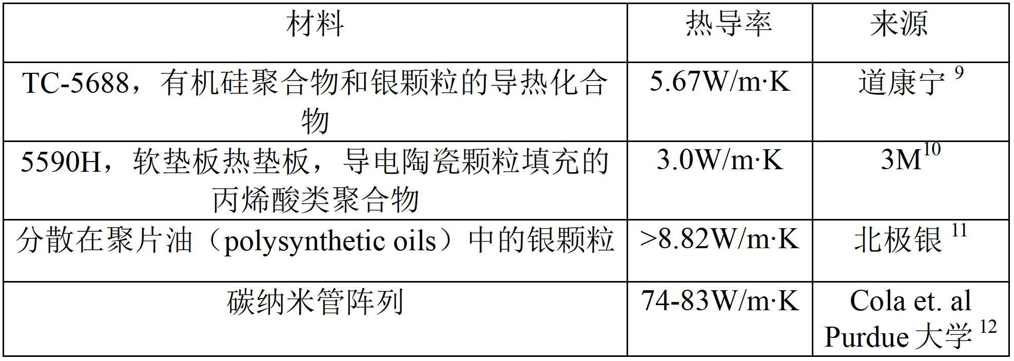
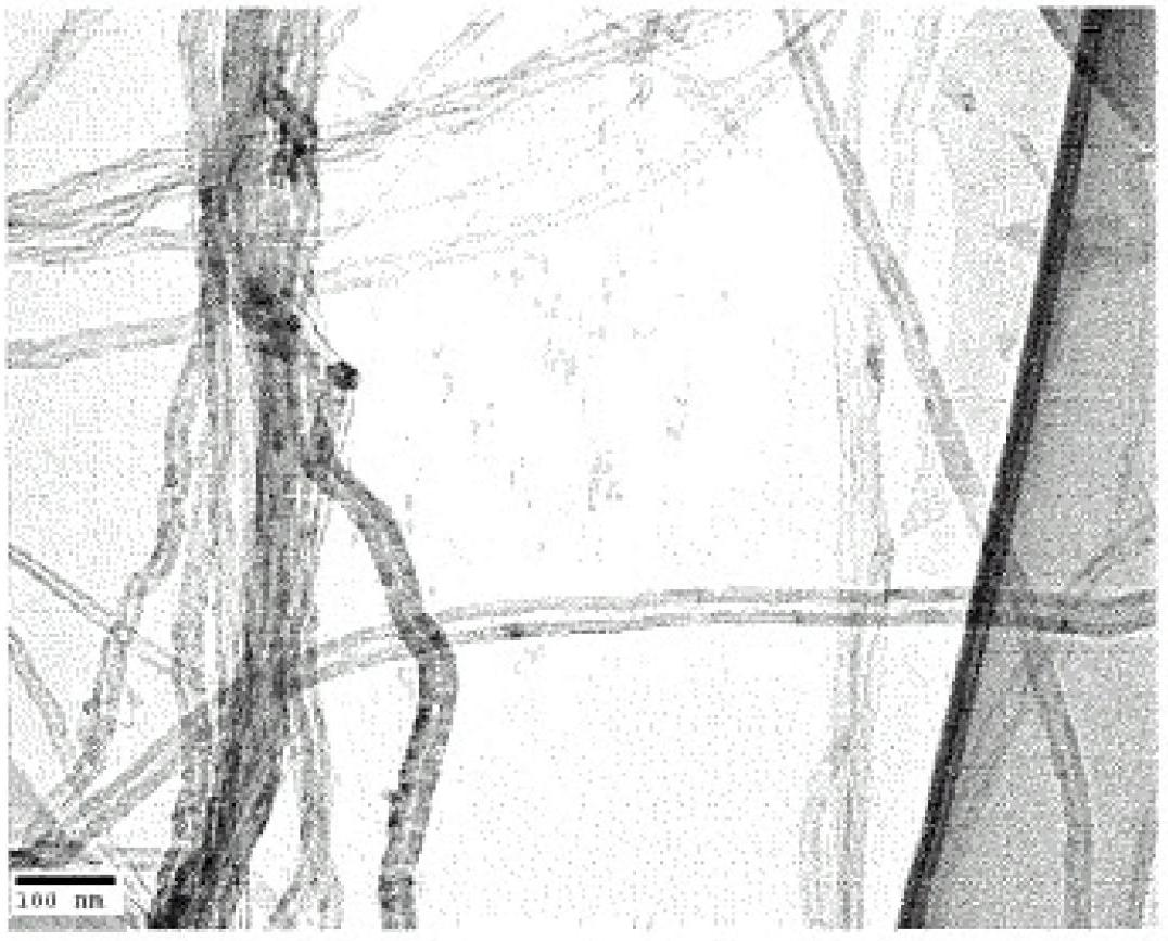
[0032] First, carbon nanotubes (CNTs) have excellent heat transfer properties. Embodiments of carbon nanotube arrays for use as thermal interface materials will be described in this disclosure, but it should be understood that other carbon nanostructures may be used as appropriate. In the present invention, thermal interface materials provide enhanced and efficient heat transfer between interfaces. With regard to carbon nanotube type adhesives, there is a relationship between heat transfer, electron conduction and adhesion. The design of the carbon nanotube-based thermal interface material ("TIM") of the present invention is based on the quantitative study of the mechanical, electrical and thermal properties of carbon nanotubes. The present invention can be synthesized on geometries suitable for integration with existing radiator systems. In one embodiment, aligned multi-walled carbon nanotubes (MWCNTs) are synthesized to enhance more efficient heat transfer properties. In ...


PUM

PropertyMeasurementUnit
thicknessaaaaaaaaaa
bulk modulusaaaaaaaaaa

Abstract

A method of implementing a carbon nanotube thermal interface material onto a heat sink that includes growing carbon nanotubes on said heat sink by chemical vapor deposition and compressing the carbon nanotubes onto metallic surfaces to increase a contact surface area between the carbon nanotubes and the metallic surfaces. The increase in the contact surface area is the area of the carbon nanotubes that is in contact with the metallic surfaces.

Description

technical field [0001] Certain embodiments of the invention relate to carbon nanotubes. More specifically, certain embodiments of the present invention relate to carbon nanotube-based thermal interface materials. Background technique [0002] Continuing advances in microelectronic devices have resulted in smaller circuit boards and the dramatic development of processors with greater speed and computing power. Due to these new developments, the total heat generated per unit area on the board has also increased. Therefore, overheating is one of the main causes of electronic failure in microelectronic devices. [0003] To solve the problem of overheating, heat sinks are used to remove heat from electronic devices. However, even the best heatsinks cannot dissipate heat effectively unless there is close contact between the processor unit and the heatsink. Thermal interface materials ("TIMs") are used for this purpose. These thermal interface materials flow and conform to the...

Claims


Application Information

Patent Timeline
Patent Type & Authority Applications(China)
IPC IPC(8): C23C16/26C01B31/02B82B3/00
CPCC23C16/01H01L23/373C23C16/56C23C16/26H01L2924/0002Y10T428/30Y10T428/2848H01L2924/00
Inventor A·迪诺杰瓦拉S·塞西
Owner THE UNIVERSITY OF AKRON
Learn More