Adjustable-frequency resonance microwave reaction chamber with open top

A technology of microwave response and frequency, applied in the field of resonant microwave reaction chamber, can solve the problems of frequency reconfigurability, inconvenient use, high cost, etc., and achieve the effect of continuous frequency adjustment, optimized reflection coefficient, and simple structure

Inactive Publication Date: 2012-10-03
UNIV OF ELECTRONICS SCI & TECH OF CHINA
View PDF3 Cites 15 Cited by
  • Summary
  • Abstract
  • Description
  • Claims
  • Application Information

AI Technical Summary

Problems solved by technology

[0007] (3) In order to achieve relevant reaction conditions under limited input power, the existing microwave reaction chamber is usually realized by resonance, and resonance also means that it can only work at a specific frequency
To sum up, the existing resonant reaction chamber can only work normally at one frequency, which cannot meet the requirement of reconfigurable frequency. It can only cover several discrete operating frequencies through multiple reaction chambers of different sizes, which is expensive and inconvenient to use.

Method used


Image

  • Adjustable-frequency resonance microwave reaction chamber with open top
  • Adjustable-frequency resonance microwave reaction chamber with open top
  • Adjustable-frequency resonance microwave reaction chamber with open top

Examples


Embodiment 1

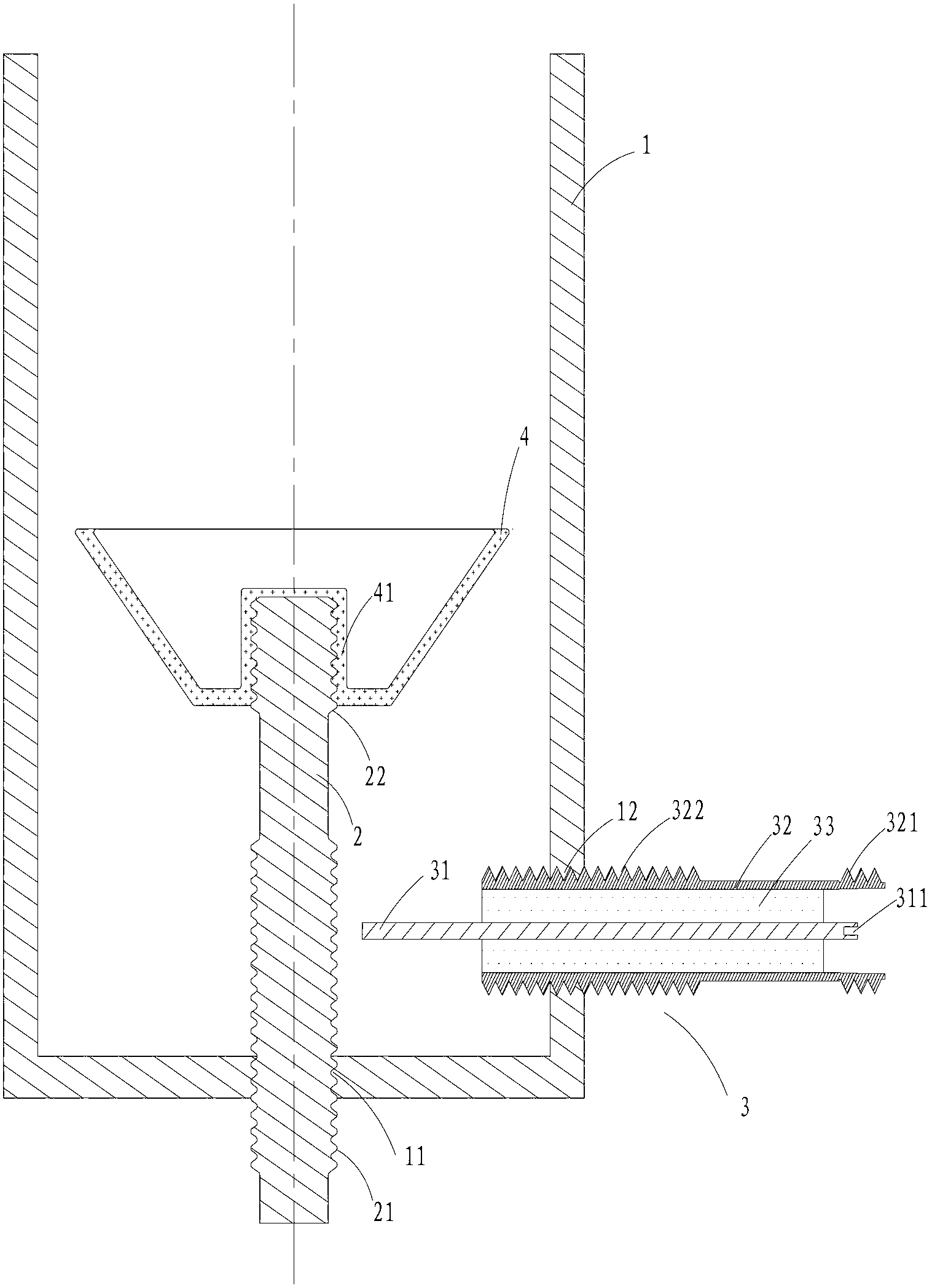
[0032] Embodiment 1: as figure 1 As shown, a frequency-tunable resonant microwave reaction chamber with an open top includes an outer conductor 1 , an inner conductor 2 , a feed coaxial 3 , and a tray 4 . The outer conductor 1 is a semi-closed cylindrical metal cavity with an open top, and there is a bottom hole 11 in the center of the bottom; the axis-rotationally symmetrical inner conductor 2 enters the interior of the outer conductor 1 through the bottom hole 11, and the lower half of the inner conductor 2 has a The frequency modulation thread 21 cooperates with the thread on the wall of the bottom hole 11 to keep the outer conductor 1 and the inner conductor 2 in electrical contact, and the length of the inner conductor 2 entering the outer conductor 1 can be adjusted at the same time. There is a side hole 12 near the bottom of the side wall of the outer conductor 1, the height of which is one-fiftieth of the wavelength corresponding to the center frequency of the adjustab...

Embodiment 2

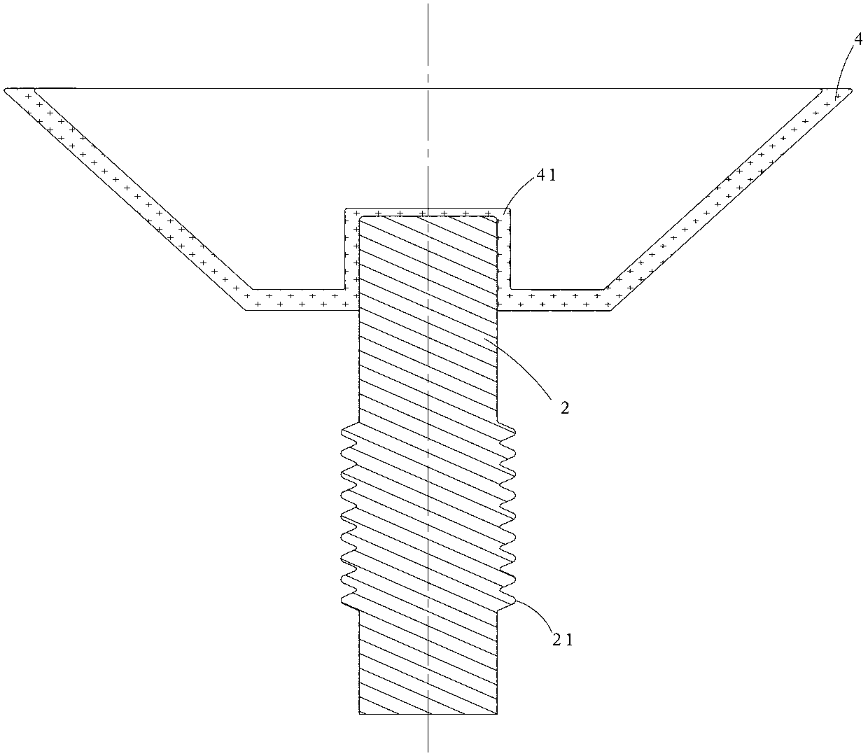
[0040] Embodiment 2: as figure 1 and figure 2 As shown, on the basis of Embodiment 1, the bottom end of the above-mentioned conical tray 4 has a concave cylinder 41, which directly fits (fits) and fixes with the top of the inner conductor 2 .

Embodiment 3

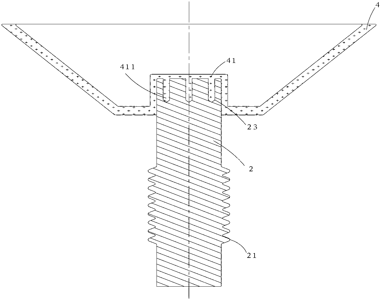
[0041] Embodiment 3: as figure 1 , image 3 and Figure 4 As shown, on the basis of Embodiment 1, the bottom end of the above-mentioned conical tray 4 has a concave cylinder 41, and its top protrudes downwards from three fixed small cylinders 411, which are connected with the three concave cylinders at the top of the inner conductor 2. The small hole 23 fits and is fixed; the bottom of the concave cylindrical small hole 23 is tapered.


PUM


Abstract

An adjustable-frequency resonance microwave reaction chamber with an open top belongs to the technical field of microwave energy application, and comprises an outer conductor (1), an inner conductor (2), a feeding coaxial body (3) and a pallet (4), wherein the top of the outer conductor (1) is open; the outer conductor (1) adopts a semi-sealed cylindrical metal cavity; the inner conductor (2) enters into the outer conductor (1) after penetrating a bottom hole (11); the feeding coaxial body (3) enters into the outer conductor (1) after penetrating a side hole (12); and the pallet (4) is fixed at the top end of the inner conductor (2). The reaction chamber manufactured by adopting the principle of a quarter-wave coaxial resonant cavity has the advantages that the frequency can be reconstructed in a wider range; and the frequency regulation method is continuous with no blind area; and the structure is simple. Therefore, the reaction chamber is suitable for the research and the application of wide-band microwave reaction, and has an application value in accurately cognizing the effect of frequency on microwave reaction and instructing related technology.

Description

technical background [0001] The invention belongs to the technical field of microwave energy application and relates to a resonant microwave reaction cavity with adjustable frequency. Background technique [0002] At present, high-power microwaves have been widely used in heating, medical treatment, drying, coating, environmental protection, auxiliary extraction and other occasions, and achieved better results. In order to understand the basic principles of microwave energy application and microwave chemical reaction, researchers need to use microwave reaction devices to study the reaction mechanism of a small amount of samples under different conditions, and finally guide large-scale industrial applications. [0003] With the deepening of research and application, it is found that microwave frequency is very important to the reaction effect. For example, the microwave absorption of a certain sample is related to the microwave frequency, that is, at a certain frequency, mic...

Claims


Application Information

Patent Timeline
Patent Type & Authority Applications(China)
IPC IPC(8): B01J19/12
Inventor 樊勇程钰间王磊夏支仙
Owner UNIV OF ELECTRONICS SCI & TECH OF CHINA
Why Eureka
Try Eureka