Automatic interior-angle chamfering machine

An internal angle machine and automatic technology, applied in the direction of driving devices, metal processing machinery parts, clamping, etc., can solve the problems of high labor intensity, high cost, low work efficiency, etc., to reduce labor intensity, improve service life, and automation intensity high effect

Inactive Publication Date: 2012-10-03
YIZHENG RUNYANG MACHINERY
View PDF0 Cites 1 Cited by
  • Summary
  • Abstract
  • Description
  • Claims
  • Application Information

AI Technical Summary

Problems solved by technology

The existing processing method is: the operator holds the piston ring to be processed, presses it into the ring grinding, turns on the pedal, rotates the main shaft, feeds the tool with the carriage, and takes out the processed ring after completion. This method depends entirely on the operation. Inexperienced workers, outdated technology, large randomness, unguaranteed quality, high labor intensity, and low work efficiency
In addition, there are imported equipment, but the cost is high

Method used


Image

  • Automatic interior-angle chamfering machine
  • Automatic interior-angle chamfering machine
  • Automatic interior-angle chamfering machine

Examples


Embodiment Construction

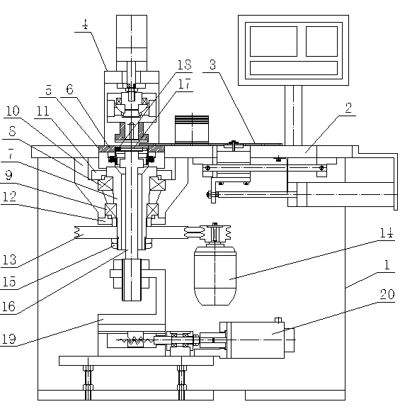
[0013] like figure 1 As shown, it is an automatic chamfering machine, including a frame 1, a panel 2 is set above the frame 1, a feeding device 3 and a pressing device 4 are set on the panel 2, a mold installation port 5 is set on the panel 2, and the mold installation port 5 The mold 6 is set, the hollow main shaft 7 is connected to the bottom of the mold 6, the hollow main shaft 7 is connected to the main shaft mounting seat 10 through the upper tapered roller bearing 8 and the lower tapered roller bearing 9, the main shaft mounting seat 10 is connected to the panel 2, and the mold 6 is set on the main shaft In the mounting seat 10, an upper bearing gland 11 is arranged above the upper tapered roller bearing 8, and the upper bearing gland 11 is connected with the main shaft mounting seat 10, and a lower bearing gland 12 is arranged below the lower tapered roller bearing 9, and the lower bearing The cover 12 is connected with the spindle mounting base 10 . The hollow main sh...


PUM


Abstract

The invention provides an automatic interior-angle chamfering machine, relates to mechanical processing equipment, and in particular relates to a device for carrying out interior-angle chamfering on piston rings. The automatic interior-angle chamfering machine comprises a machine frame, a panel is arranged above the machine frame, a feeding device and a swaging device are arranged on the panel, a mould mounting opening is arranged on the panel, and a mould is arranged in the mould mounting opening. A hollow spindle is connected below the mold, the hollow spindle is connected with a spindle mounting seat through an upper cone roller bearing and a lower cone roller bearing, and the spindle mounting seat is connected with the panel. An upper bearing pressing cover is arranged above the upper cone roller bearing, and a lower bearing pressing cover is arranged under the lower cone roller bearing. The hollow spindle under the spindle mounting seat is connected with a spindle belt pulley, the spindle belt pulley is connected with a power device, and the hollow spindle under the spindle belt pulley is in threaded connection with a round nut. Cutter frame shafts penetrate through the hollow spindle at intervals, the upper ends of the cutter frame shafts are connected with a cutter frame, the cutter frame is connected with a cutter, and the cutter is arranged in the mould. The lower end of the cutter frame shaft is connected with a stepping motor through a connecting piece. The automatic interior-angle chamfering machine is high in efficiency and low in cost.

Description

technical field [0001] The invention relates to machining equipment, in particular to a device for chamfering inner corners of piston rings. Background technique [0002] The piston ring is a non-circular metal ring with an opening, and a metal elastic ring with a large outward expansion deformation, which is assembled into the cross-section and its corresponding annular groove. After the piston ring is finished, it must be chamfered inside the piston ring. The existing processing method is: the operator holds the piston ring to be processed, presses it into the ring grinding, turns on the pedal, rotates the main shaft, feeds the tool with the carriage, and takes out the processed ring after completion. This method depends entirely on the operation. The experience of the workers, the technology is backward, the randomness is large, the quality cannot be guaranteed, the labor intensity is high, and the work efficiency is low. There are also imported equipment, but the cost ...

Claims


Application Information

Patent Timeline
Patent Type & Authority Applications(China)
IPC IPC(8): B23D79/00B23Q3/00B23Q7/00B23Q5/04B23Q5/32
Inventor 陶俊周广才季国宝刘久群
Owner YIZHENG RUNYANG MACHINERY
Why Eureka
Try Eureka