Numerical control equipment
A kind of numerical control equipment and combined technology, applied in the field of numerical control machine tools, can solve the problems that multiple tools cannot be used at the same time, the main support part and the base are not vertical, the main support part is easy to deform, etc., and achieve simple structure, good bearing effect and rigidity Good results
- Summary
- Abstract
- Description
- Claims
- Application Information
AI Technical Summary
Problems solved by technology
Method used
Image
Examples
Embodiment 1
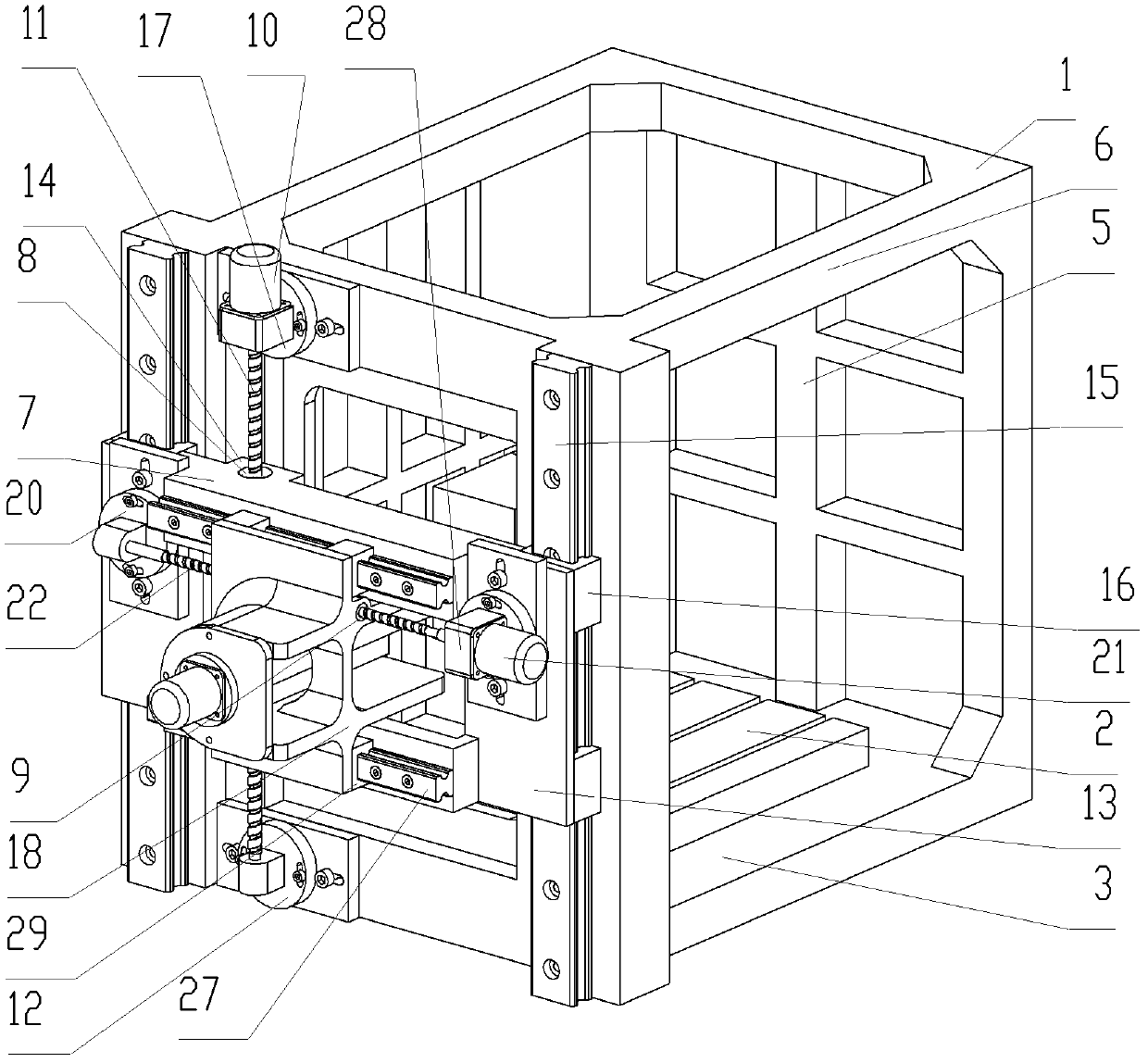
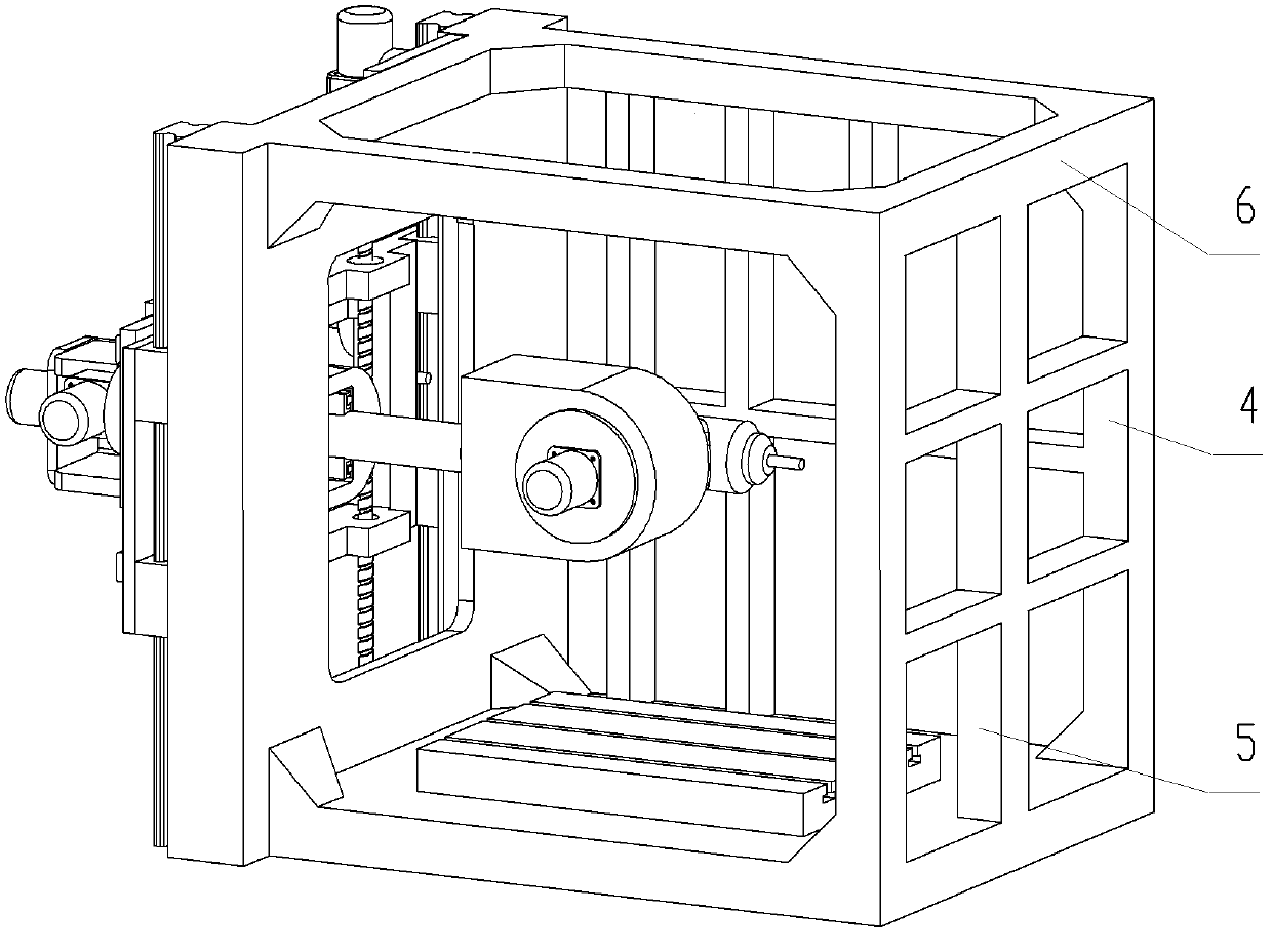
[0070] Such as Figure 1 to Figure 5 As shown, a CNC machine tool includes an integrally formed main body frame 1 and a workbench 2 . The main body frame 1 includes a square base 3 , main support columns 4 integrally formed with the base 3 and arranged at four corners of the base 3 , and connecting parts 5 respectively arranged at the middle positions of the right side and the rear side of the base 3 . The connecting part 6 is formed integrally with the main support column 4 and is arranged on the upper part of the main support column 4 . The left side and the front side of the main body frame 1 are square closed-loop structures with openings facing the horizontal direction. The two main support columns 4 and the connection part 6 placed on the left side of the base 3 form the first main support part, and the two main support columns 4 and the connection part 6 placed on the right side of the base 3 form the second main support part. The front side of a main support part and...
Embodiment 2
[0084] Such as Figure 6 As shown, the difference from Embodiment 1 is that the second sliding seat 50 includes a second sliding seat plate 51, a cylindrical first guide sleeve 52 protruding from the left side of the second sliding seat plate 51, and a circular tube-shaped first guide sleeve 52 extending from the second sliding seat plate 51. The circular tube-shaped second guide sleeve 53 protrudingly provided on the right side of the plate 51, the outer periphery of the second slide seat plate 51 is square, and the circular tube-shaped first guide sleeve 52 and the circular tube-shaped second guide sleeve 53 protrude from the periphery.
[0085] The lateral spindle device includes a circular guide rod 56 that can move back and forth in the horizontal direction, an end cover 57, a rotating shaft 58 that is installed in the guide rod 56 and can only rotate relative to the guide rod 56, a first rotor 59 that drives the rotating shaft 58 to rotate, and a first Stator 60 , bearin...
Embodiment 3
[0087] Such as Figure 7 to Figure 9 As shown, the difference from Embodiment 1 is that the second slider 70 includes a second slider plate 71, the first protrusion 72 protrudes from the left side of the second slider plate 71, and the second convex portion 72 protrudes from the right side of the second slider plate 71. The second convex portion 73 protrudes from the side. A fixing plane 74 is provided on the outer surfaces of the first protrusion 72 and the second protrusion 73 , and a side protrusion 75 is provided on the fixing plane 74 . The outer periphery of the second sliding seat plate 71 is square, and the first protrusion 72 and the second protrusion 73 protrude from the periphery. In the second sliding seat 70, a round hole 78 and a square hole 79 passing through the first convex portion 72, the second sliding seat plate 71, and the second convex portion 73 are provided. The round hole 78 is placed in the center of the square hole 79, and the circle The diameter o...
PUM
 Abstract
Description
Claims
Application Information
 - R&D
- Intellectual Property
- Life Sciences
- Materials
- Tech Scout
- Unparalleled Data Quality
- Higher Quality Content
- 60% Fewer Hallucinations
Browse by: Latest US Patents, China's latest patents, Technical Efficacy Thesaurus, Application Domain, Technology Topic, Popular Technical Reports.
© 2025 PatSnap. All rights reserved.Legal|Privacy policy|Modern Slavery Act Transparency Statement|Sitemap|About US| Contact US: help@patsnap.com


