Continuous pultrusion manufacturing method and production device for fibrous composite drive shaft

A technology of fiber composite material and manufacturing method, which is applied in the field of continuous pultrusion manufacturing method of fiber composite transmission shaft and its production device, can solve the problems of difficult control of glue content, poor strength and stiffness, and low production efficiency, and achieve Avoid the difficult control of glue content, improve the axial stiffness, and improve the effect of production efficiency

Active Publication Date: 2012-10-03
HENGSHEN
View PDF6 Cites 29 Cited by
  • Summary
  • Abstract
  • Description
  • Claims
  • Application Information

AI Technical Summary

Problems solved by technology

[0005] The purpose of the present invention is to provide a continuous pultrusion manufacturing method of fiber composite transmission shaft and its production device to solve the problems of low precision, poor uniformity, poor strength and stiffness, and production efficiency in the existing

Method used


Image

  • Continuous pultrusion manufacturing method and production device for fibrous composite drive shaft
  • Continuous pultrusion manufacturing method and production device for fibrous composite drive shaft

Examples


Embodiment 1

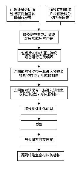
[0054] like figure 1 As shown, this embodiment provides a continuous pultrusion manufacturing method for a fiber composite transmission shaft, including the following production steps:

[0055] The preparation of the prepreg tape, the prepreg tape is obtained by impregnating the resin matrix from the carbon fiber yarn cluster;

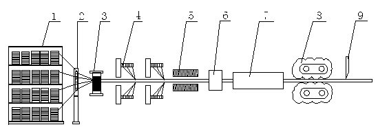
[0056] The mold is preformed, and the prepreg tape is unwound by the hoop winding disc at a winding angle of 30° to form a hoop wrap. The wrapped yarn is woven online through two braiding rollers, and enters the temperature together with the axial prepreg tape. Preforming a preforming mold at 80°C to form a preform;

[0057] Curing molding, the prefabricated body preformed by the preforming mold enters the curing molding mold with three stages of heating, namely heating, gelling and curing, to form the transmission shaft rod;

[0058] Mechanical processing, pull the transmission shaft rod out of the solidified molding mold at a traction speed of 10cm...

Embodiment 2

[0070] like figure 1 As shown, a continuous pultrusion manufacturing method of a fiber composite transmission shaft comprises the following production steps:

[0071] Preparation of the prepreg tape, the sheet prepreg material is cut into prepreg tapes with a width of 4-12mm by a cutting machine;

[0072] The mold is preformed, and the prepreg tape is unwound by the hoop winding disc at a winding angle of 70° to form a hoop wrap. The wrapped yarn is woven online through two braiding rollers, and enters the temperature together with the axial prepreg tape. Preforming the preforming mold at 150°C to form a prefabricated body;

[0073] Curing molding, the prefabricated body preformed by the preforming mold enters the three-stage heating curing molding mold for curing molding to form a transmission shaft rod;

[0074] Mechanical processing, pulling the transmission shaft rod out of the solidified molding mold at a traction speed of 30cm / min through the traction mechanism, cuttin...


PUM

PropertyMeasurementUnit
Winding angleaaaaaaaaaa

Abstract

The invention provides a continuous pultrusion manufacturing method for a fibrous composite drive shaft. The continuous pultrusion manufacturing method comprises the following steps: preparing a pre-dipping belt, pre-forming a mould, curing and forming, and mechanically processing. A production device for the fibrous composite drive shaft comprises a yarn creel, a pre-forming mould, a curing and forming mould, a traction mechanism and a cutting mechanism, wherein the yarn creel and the pre-forming mould are provided with a winding and braiding mechanism respectively; the winding and braiding mechanism comprises a yarn collecting plate, an annular winding disc and at least one braiding roller which are arranged in sequence; and an infrared heater is also arranged between the braiding roller and the pre-forming mould. According to the invention, a rod piece of a drive shaft can be directly subjected to pultrusion through a mould without the traditional gum dipping process and is cut and gummed so as to finish the production of the fibrous composite drive shaft, so that the production cost of the fibrous composite drive shaft is reduced, and meanwhile, the defects of difficultly controlled gum content and high gum waste in the traditional gum dipping process, easily damaged fibers and the like are avoided, and the production quality is improved.

Description

technical field [0001] The invention relates to a continuous pultrusion process and a production device for producing a composite material transmission shaft through prepreg tape weaving and pultrusion molding, in particular to a continuous pultrusion manufacturing method and a production device for a fiber composite transmission shaft. Background technique [0002] The existing automobile industry, engineering machinery, ships, warships and other fields are all developing in the direction of lightweight. In practical applications, in addition to optimizing the existing structure, the application of new lightweight materials can effectively achieve the goal of lightweighting. [0003] The composite drive shaft is a structural part used to transmit torque and other dynamic loads. Because of its high specific strength, specific stiffness, excellent shock absorption performance, fatigue resistance, corrosion resistance, non-magnetic conductivity, and low noise, it has been Wi...

Claims


Application Information

Patent Timeline
IPC IPC(8): B29C70/52B29C70/54
Inventor 刘伟李红强仰忠轩颜磊田农
Owner HENGSHEN
Why Eureka
Try Eureka