Sludge dehumidify and drying machine

A drying machine and sludge technology, applied in the direction of dewatering/drying/concentrating sludge treatment, etc., can solve the problems of reducing oxygen content, low energy utilization rate, safety risks, etc., and achieve flexible flow adjustment and spreading effect. Uniform, long-lasting effect

Inactive Publication Date: 2014-03-12
GUANGZHOU SHINCCI ENERGY EQUIP CO LTD
View PDF5 Cites 3 Cited by
  • Summary
  • Abstract
  • Description
  • Claims
  • Application Information

AI Technical Summary

Problems solved by technology

[0004] (1) High energy consumption: sludge drying is a process of net energy consumption, and energy consumption usually accounts for more than 80% of the total cost of sludge treatment; traditional sludge drying equipment uses heating and dehumidification, and the energy utilization rate is low; Evaporating one ton of water consumes about 1.5 tons of steam and about 70kw.h of electricity;
[0005] (2) There is a safety risk. Nitrogen is usually added to reduce the oxygen content in sludge drying to avoid explosion;
[0006] (3) Not environmentally friendly: a large amount of odor is emitted, and a responsible tail gas treatment system needs to be built; the working environment of the drying workshop is poor; the heating source of the drying process is a boiler, which also emits a large amount of tail gas, and there is a problem of secondary sludge;
[0007] (4) Among them, the wet sludge molding technology is the key link of sludge drying. The current market technology is the orifice extrusion technology, but this technology is greatly affected by the friction loss of impurities (sandstone, etc.), and the sludge strips are spread Poor air permeability, difficult to adjust the amount of sludge, especially the poor adaptability of small sludge machines

Method used


Image

  • Sludge dehumidify and drying machine
  • Sludge dehumidify and drying machine
  • Sludge dehumidify and drying machine

Examples


Embodiment Construction

[0043] The present invention will be described in detail below in conjunction with the accompanying drawings and specific embodiments.

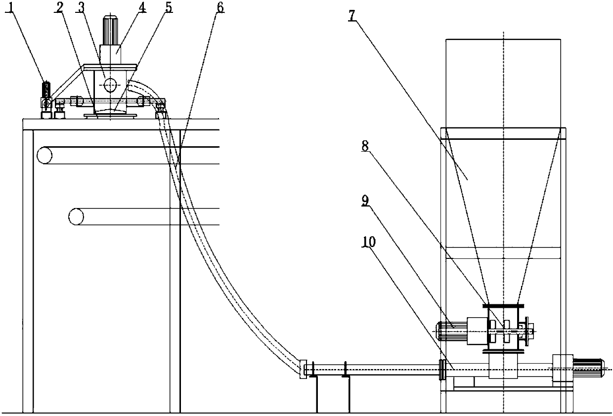
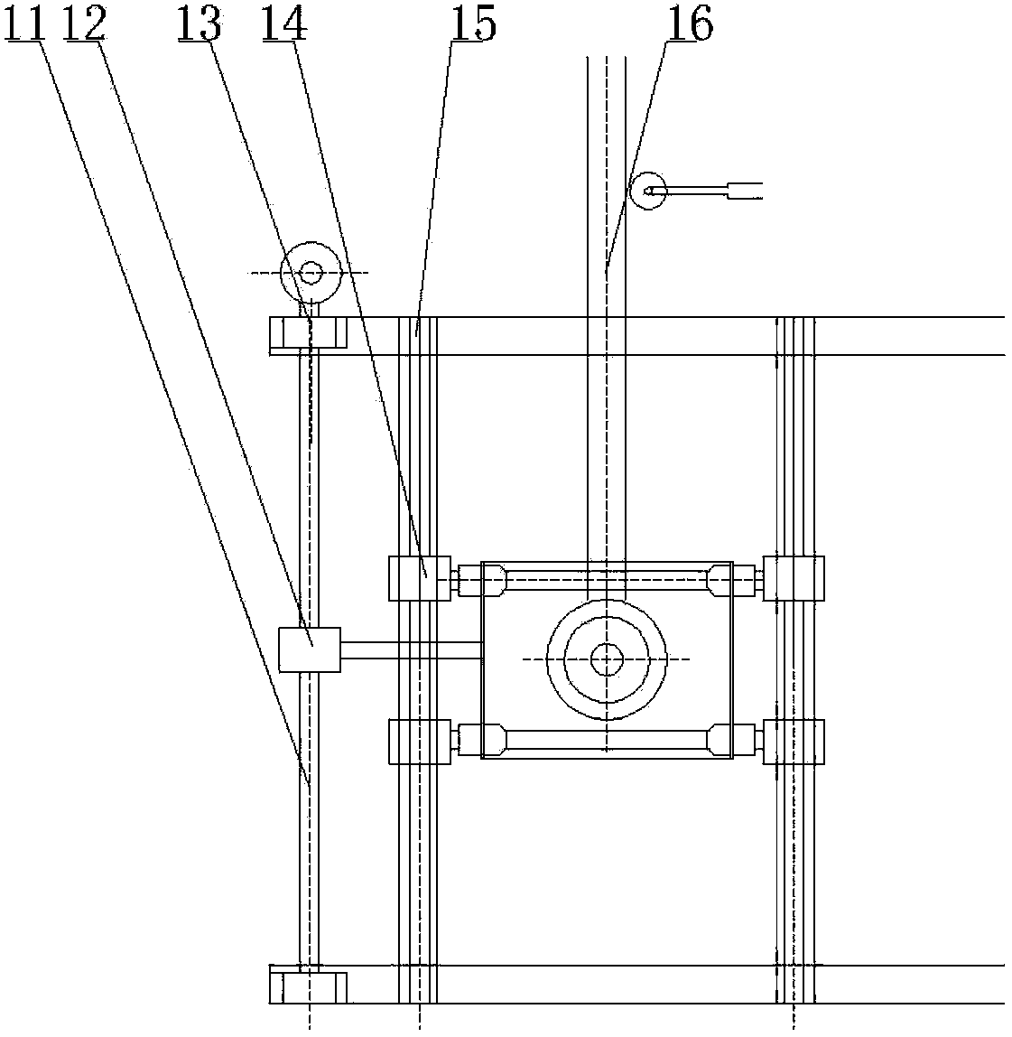
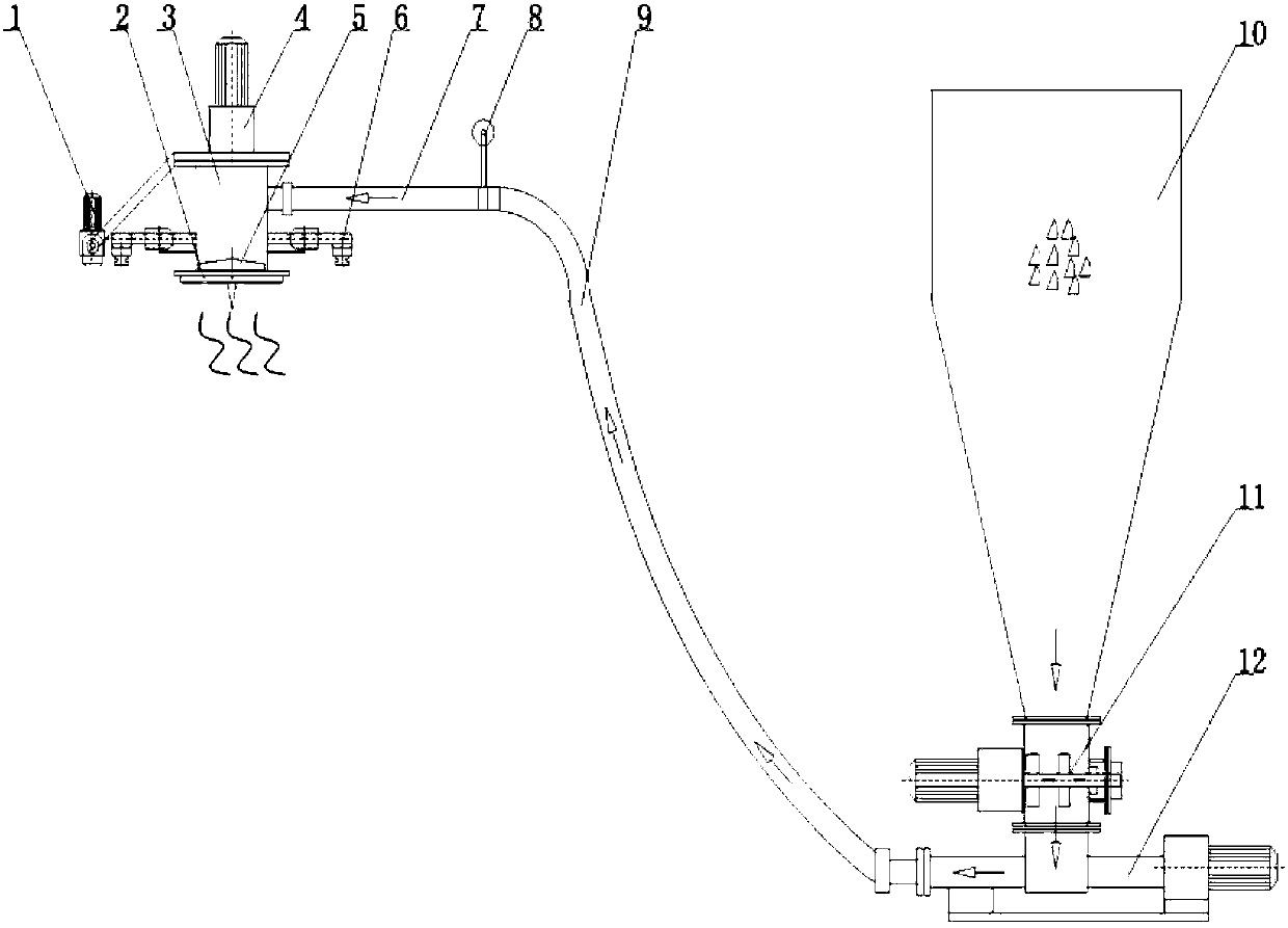
[0044] Sludge dehumidification dryer, such as Figure 5 and Figure 6 As shown, it includes an extruded strip feeding device 21, at least one layer of mesh belt and a heat pump dehumidification drying device 23, the mesh belt is arranged in the drying box 24, and the extruded strip feeding device 21 is arranged on one end of the mesh belt , used to transport the sludge to be dried to the mesh belt. The heat pump dehumidification and drying device 23 is installed in an auxiliary box on the side of the drying body 24 , and the heat pump dehumidification and drying device 23 is connected to the bottom of the drying box through an air supply pipe 33 . Wherein, the mesh belt is arranged in two layers, the first layer of mesh belt 26 and the second layer of mesh belt 27 are layered from top to bottom, and the lower part of the end of the first la...


PUM

PropertyMeasurementUnit
thicknessaaaaaaaaaa
diameteraaaaaaaaaa
thicknessaaaaaaaaaa

Abstract

The invention discloses a sludge dehumidify and drying machine, which comprises a squeezing and feeding device, at least one layer of screen belt and a thermal pump dehumidifying and drying device, wherein the screen belt is arranged in a drying box body; the squeezing and feeding device is arranged above one end of the screen belt, and is used for conveying sludge to be dried to the screen belt after squeezing; and the thermal pump dehumidifying and drying device is arranged in an auxiliary box body on the side edge of the drying box body, and is connected with the bottom of the drying box body through a blowing pipe. The sludge dehumidifying and drying machine has the advantages of energy saving, environment friendliness, wide suitability, long service life and high safety.

Description

【Technical field】 [0001] The invention relates to the field of drying equipment, in particular to a sludge dehumidification and drying machine. 【Background technique】 [0002] At present, the commonly used drying systems are mainly direct drying drum technology, multi-layer step drying technology, rotary disk drying technology, fluidized bed drying technology and so on. However, sludge belt drying has attracted widespread attention due to its strong adaptability to wet sludge, less maintenance parts, long service life, and low drying temperature, and has a good market application prospect; heat pump dehumidification combined with mesh belt drying sewage Sludge drying technology is a new trend of sludge belt drying, which has great advantages in terms of energy saving and environmental protection. Sludge heat pump dehumidification and drying technology will dominate sludge belt drying. [0003] The existing sludge dryer has the following problems: [0004] (1) High energy c...

Claims


Application Information

Patent Timeline
Patent Type & Authority Patents(China)
IPC IPC(8): C02F11/12
Inventor 石曾矿
Owner GUANGZHOU SHINCCI ENERGY EQUIP CO LTD
Why Eureka
Try Eureka