Boiler and air preheating system thereof

A technology of air preheating and air preheater, applied in the field of electric power, can solve the problems of high exhaust gas temperature, shortening the service life of air preheater, and increasing maintenance cost, etc.

Inactive Publication Date: 2012-10-03
黄绍新
View PDF8 Cites 1 Cited by
  • Summary
  • Abstract
  • Description
  • Claims
  • Application Information

AI Technical Summary

Problems solved by technology

[0003] At present, the design exhaust gas temperature of large units is generally 120°-130°C. In fact, the exhaust gas temperature of the power plant is generally higher than the design value, and the temperature of the flue gas entering the air preheater at the outlet of the economizer is relatively high. , resulting in higher heat loss
[0004] Theoretically speaking, every time the exhaust gas temperature is lowered by 10°-15°C, the boiler efficiency can be increased by about 1%. At present, the exhaust gas temperature is mainly reduced by increasing the heat transfer area of ​​the air preheater and the boiler efficiency heat exchange performance and reduce energy loss; however, there is a certain limit to reducing the exhaust gas temperature. On the one hand, when the exhaust gas temperature is relatively low, the temperature of the flue gas is further increased The temperature difference between the flue gas and the air also decreases, even if the heat transfer area of ​​the air preheater increases a lot, the heat transfer between the flue gas and the air is relatively small, which reduces the temperature drop of the flue gas; on the other hand, When the exhaust gas temperature is low, the temperature of the pipe wall of the air preheater may be lower than the dew point of the flue gas, resulting in low-temperature corrosion of the pipe wall and reducing the service life of the air preheater. It needs to be replaced once a year, and if the corrosion is serious, it needs to be replaced once every half a year, which seriously reduces the efficiency of the boiler and increases the maintenance cost.

Method used


Image

  • Boiler and air preheating system thereof
  • Boiler and air preheating system thereof

Examples


Embodiment Construction

[0020] The core of the present invention is to provide an air preheating system for a boiler, which can significantly reduce the exhaust gas temperature and improve the thermal efficiency of the boiler. Another core of the present invention is to provide a boiler comprising the above-mentioned air preheating system.

[0021] In order to enable those skilled in the art to better understand the solution of the present invention, the present invention will be further described in detail below in conjunction with the accompanying drawings and specific embodiments.

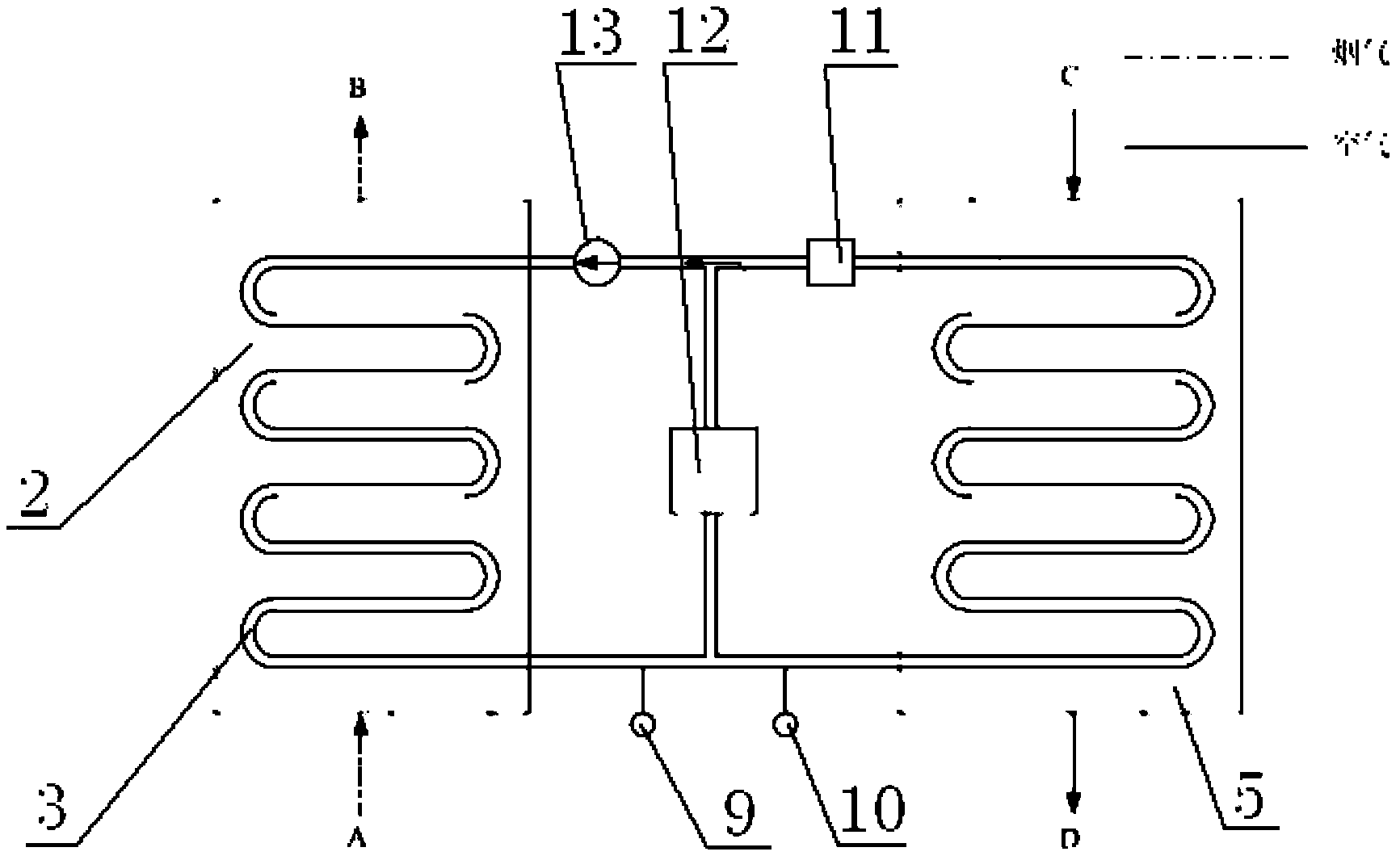
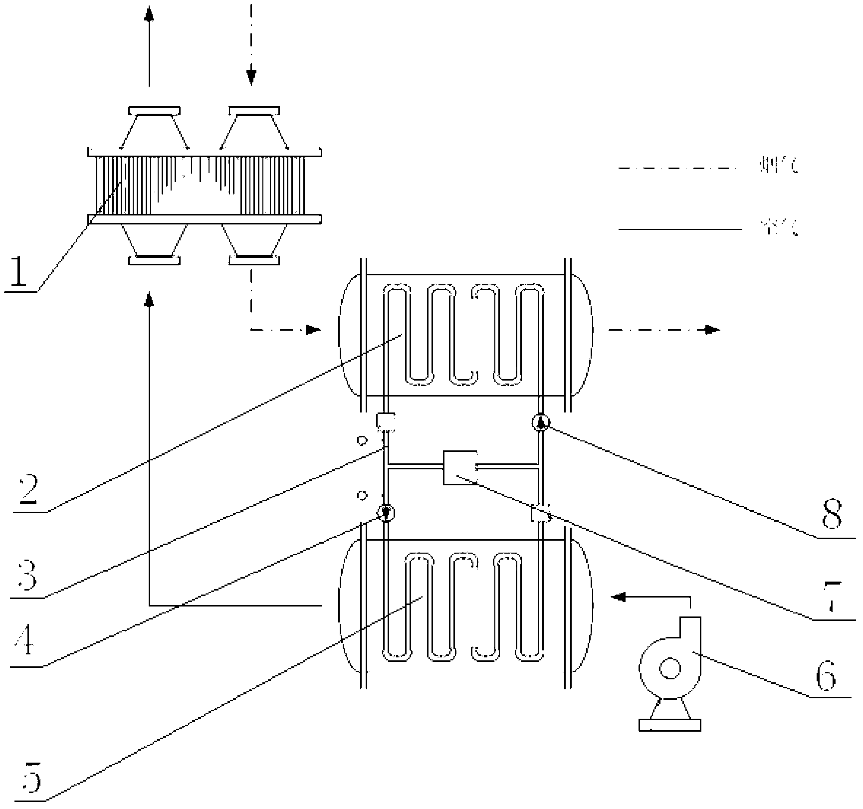
[0022] Please refer to figure 1 and figure 2 , figure 1 It is a working schematic diagram in a specific embodiment of the air preheating system provided by the present invention, figure 2 for figure 1 The schematic diagram of the closed loop circuit between the flue gas heat exchanger and the air heat exchanger in the air preheating system shown.

[0023] In a specific embodiment, the air preheating system provi...


PUM


Abstract

The invention discloses an air preheating system used for a boiler, which comprises an air preheater provided with a smoke outlet and an air inlet, wherein a smoke heat exchanger is connected at the smoke outlet of the air preheater, an air heat exchanger for heating air entering the air preheater is connected at the air inlet of the air preheater, the smoke heat exchanger forms a closed circulation loop together with the air heat exchanger via heat exchange pipes, the heat exchange pipes are filled with a heat conducting liquid, and a driving pump is arranged in the closed circulation loop. The air preheating system provided by the invention adopts closed circulation, the heat conducting liquid is used as a heat transfer medium and has relatively small heat loss and high heat transfer efficiency, so that residual heat of smoke can be fully utilized, the exhaust smoke temperature is obviously lowered, and the heat efficiency of the boiler is increased. In addition, the invention also discloses a boiler comprising the air preheating system.

Description

technical field [0001] The invention relates to the field of electric power technology, in particular to an air preheating system for a boiler. In addition, the present invention also relates to a boiler comprising the above-mentioned air preheating system. Background technique [0002] The heat loss of power plant exhaust smoke is the main part of the boiler heat loss. In order to better improve the thermal efficiency of the boiler, an air preheater is generally installed to reuse the exhausted flue gas and preheat the air before entering the boiler to a certain level. Temperature, improve the heat exchange performance of the boiler. [0003] At present, the design exhaust gas temperature of large units is generally 120°-130°C. In fact, the exhaust gas temperature of the power plant is generally higher than the design value, and the temperature of the flue gas entering the air preheater at the outlet of the economizer is relatively high. , resulting in higher heat loss. ...

Claims


Application Information

Patent Timeline
Patent Type & Authority Applications(China)
IPC IPC(8): F23L15/00
CPCY02E20/34
Inventor 向文国黄进黄绍新
Owner 黄绍新
Why Eureka
Try Eureka