Magnetic cold storage device for magnetic refrigerator
A magnetic refrigerator and magnetic cold storage technology, which is applied to refrigerators, machines using electric/magnetic effects, refrigeration and liquefaction, etc., to achieve the effects of improving conversion efficiency, good economy, and compact structure
- Summary
- Abstract
- Description
- Claims
- Application Information
AI Technical Summary
Problems solved by technology
Method used
Image
Examples
Embodiment 1
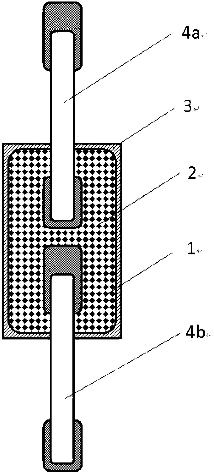
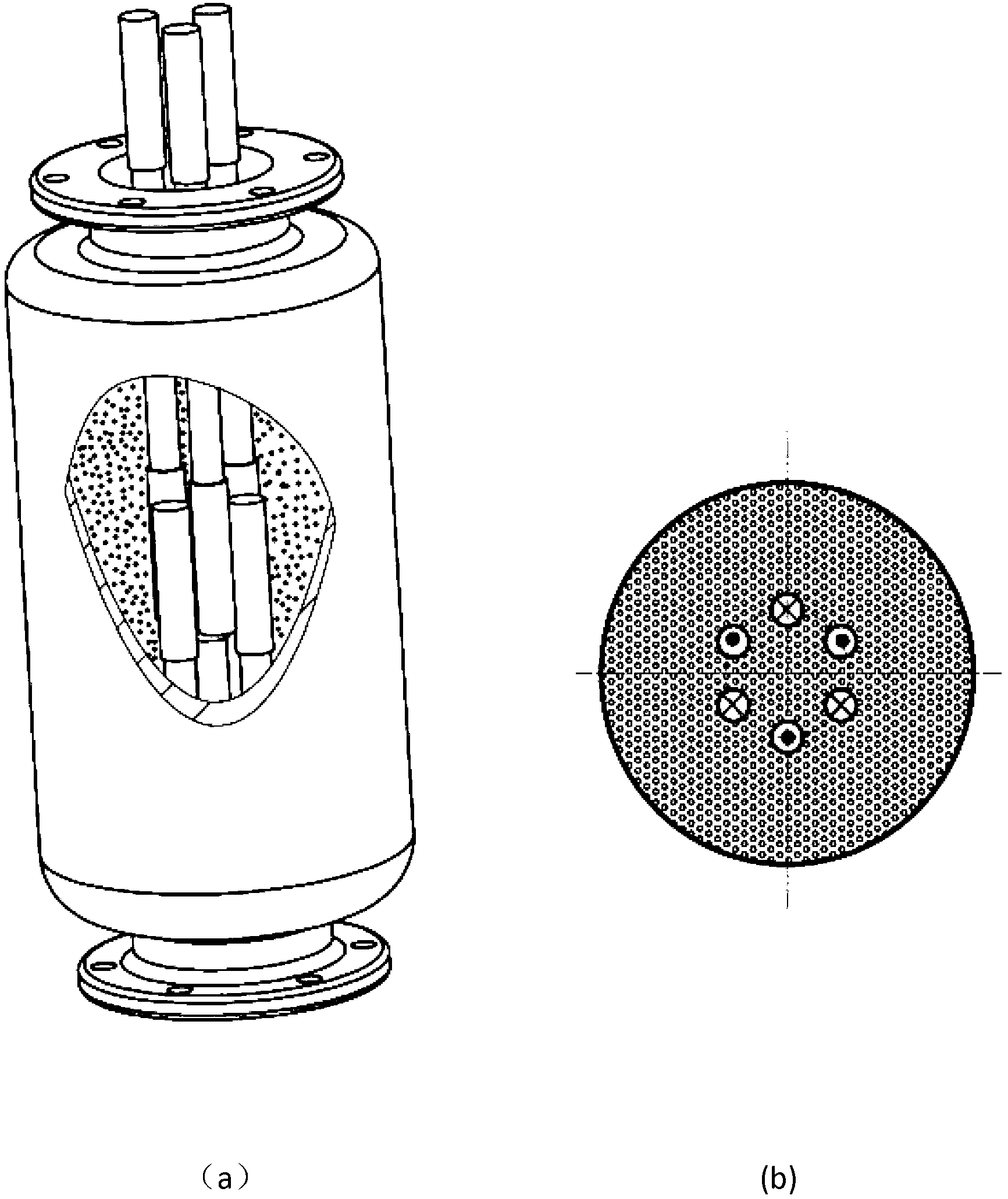
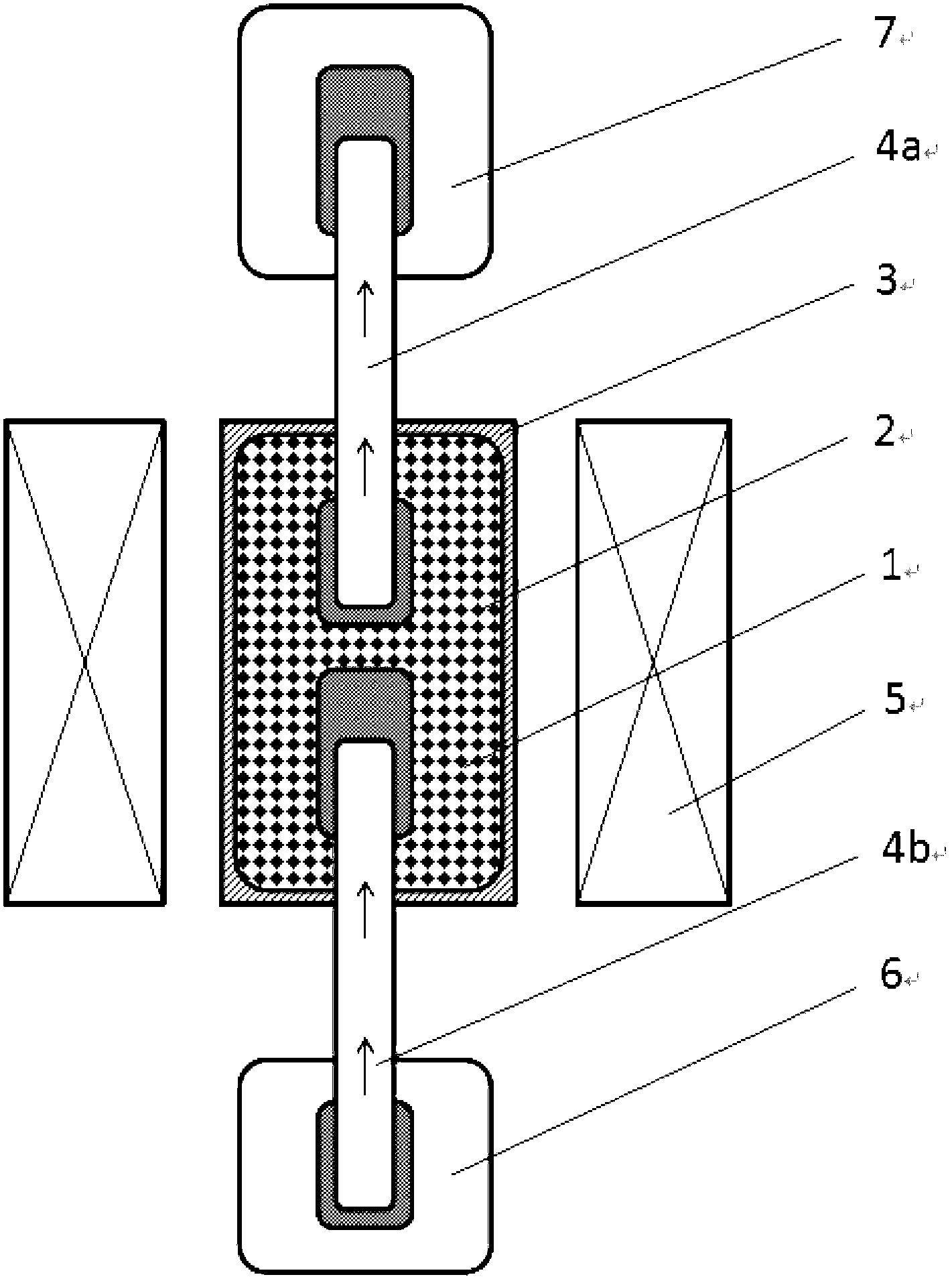
[0036] One of the embodiments of the thermal switch magnetic cold storage device of the magnetic refrigerator of the present invention is: a thermal diode is used as the thermal switch unit, such as image 3 shown. It is placed in the periodic magnetic field provided by the controllable magnetic field source 5 by the magnetic regenerator 3. The upper and lower ends of the magnetic regenerator 3 are respectively connected to a thermal diode 4a, 4b, wherein the evaporation section of the thermal diode 4a is placed in the magnetic regenerator. 3, the condensation section is set at the upper part of the magnetic cold storage 3 and contacts the heat source 7; the condensation section of the thermal diode 4b is placed inside the magnetic cold storage 3, and the evaporation section is set at the lower part of the magnetic cold storage 3 and is in contact with the cold source 6. At the same time, the magnetic cold storage The outer wall of the device 3 and the outer wall of the therma...
Embodiment 2
[0041] The second embodiment of the thermal switch magnetic cold accumulator of the magnetic refrigerator of the present invention is as follows: Figure 4 As shown, one end of the magnetic cold storage adopts a thermal diode type thermal switch, and the other end is connected with pipes, valves, pumps and heat exchangers to form a circulation circuit. It is placed in the periodic magnetic field provided by the controllable magnetic field source 5 by the magnetic regenerator 3. The lower end of the magnetic regenerator 3 is connected to the thermal diode 4, wherein the condensation section of the thermal diode 4 is located inside the magnetic regenerator 3, and its evaporation section is located in the magnetic regenerator. The lower part of the regenerator 3 is in contact with the cold source 6; the upper end of the magnetic regenerator 3 is connected to the pipeline 11, and forms a circulation circuit with the valve 10, the pump 9 and the heat exchanger 8, wherein the heat ex...
Embodiment 3
[0049] The following illustrates the structure of a thermal switch unit adopted by the device of the present invention, as Figure 5 shown. It is a slender, hollow, closed metal tube filled with working fluid. Figure 5 The inner wall of the thermal diode tube is a light pipe structure, and the outer wall of the upper and lower ends is a fin structure to enhance heat transfer. A capillary wick structure can also be arranged inside the heat pipe.
[0050] The tube wall of the heat pipe is made of metal materials such as stainless steel or copper, and the working medium in the tube can be fluids such as water, acetone, ammonia, and liquid nitrogen. The choice of working fluid should be based on the temperature range used by the heat pipe. On this premise, the compatibility between the working fluid and the tube wall and capillary core of the heat pipe should be stable, and it should have good thermal stability, high latent heat and thermal conductivity, and relatively low vis...
PUM
 Abstract
Description
Claims
Application Information
 - R&D
- Intellectual Property
- Life Sciences
- Materials
- Tech Scout
- Unparalleled Data Quality
- Higher Quality Content
- 60% Fewer Hallucinations
Browse by: Latest US Patents, China's latest patents, Technical Efficacy Thesaurus, Application Domain, Technology Topic, Popular Technical Reports.
© 2025 PatSnap. All rights reserved.Legal|Privacy policy|Modern Slavery Act Transparency Statement|Sitemap|About US| Contact US: help@patsnap.com


