
High-pressure resistant lamella heat exchanger adopting round corrugated plates

A corrugated plate and heat exchanger technology, applied in the field of heat exchangers, can solve the problems of design waste, volume and material waste, design mismatch, etc., and achieve the effect of wide material selection, strong applicability, and simple and compact overall structure

Inactive Publication Date: 2012-10-03
HARBIN ENG UNIV
View PDF8 Cites 9 Cited by
  • Summary
  • Abstract
  • Description
  • Claims
  • Application Information

AI Technical Summary

Problems solved by technology

[0003] In ordinary plate heat exchangers, the channel structures of the two media are the same. For some working conditions where the physical properties of the heat exchange media on both sides are quite different, there will be design mismatches, which will result in waste of volume and materials.
For example, when using water to cool high-viscosity lubricating oil, since the viscosity of the lubricating oil is much higher than that of water, the flow resistance of the lubricating oil will be much higher than that of the cooling water at the same flow rate, and usually the flow resistance of the lubricating oil meets the design requirements When the upper limit is reached, the flow resistance on the cooling water side is far from reaching the limit, which causes design waste

Method used


Image

  • High-pressure resistant lamella heat exchanger adopting round corrugated plates
  • High-pressure resistant lamella heat exchanger adopting round corrugated plates
  • High-pressure resistant lamella heat exchanger adopting round corrugated plates

Examples


Embodiment Construction

[0024] The present invention is described in more detail below in conjunction with accompanying drawing example:

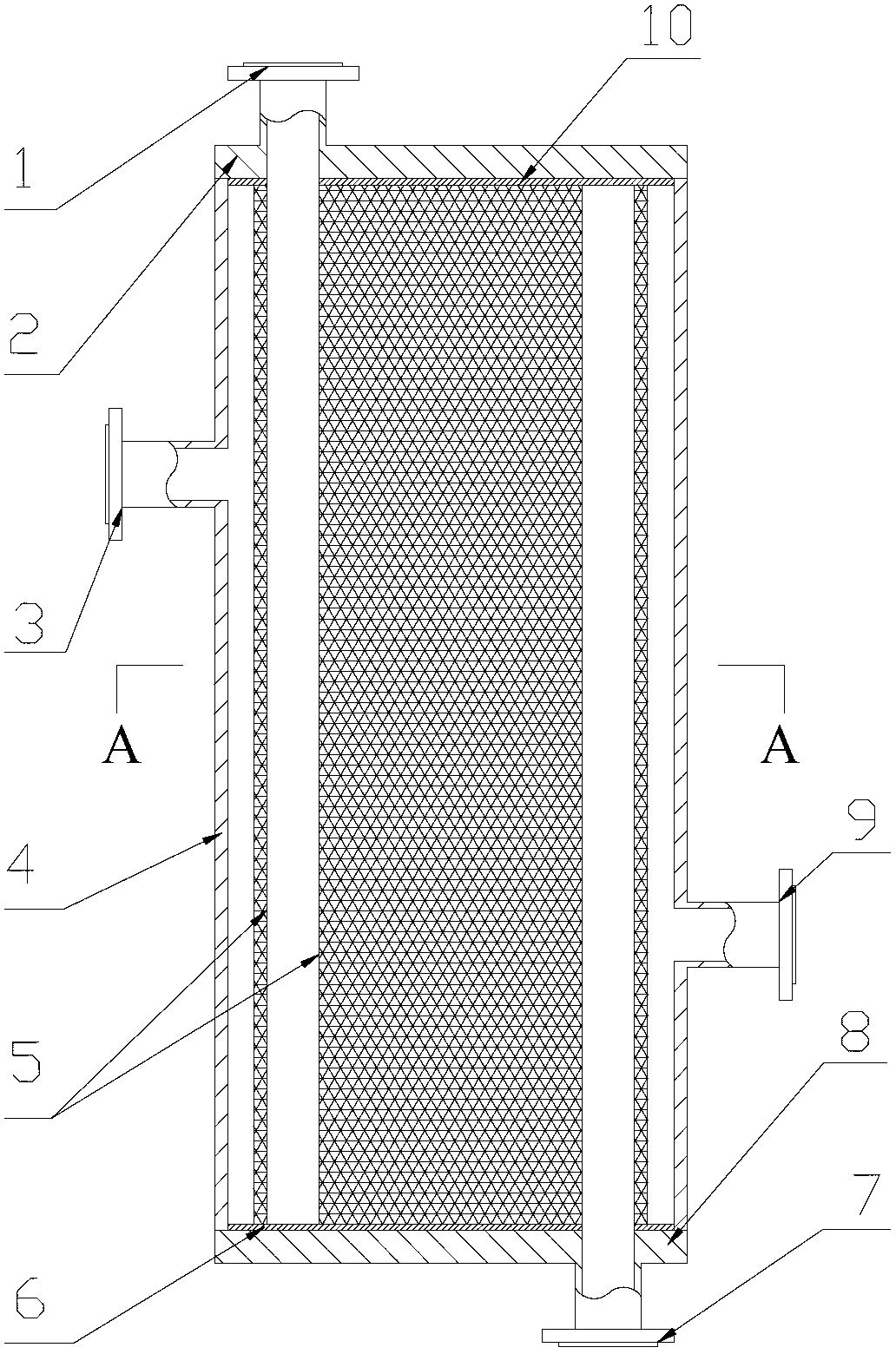
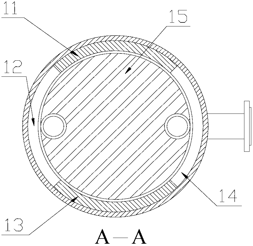
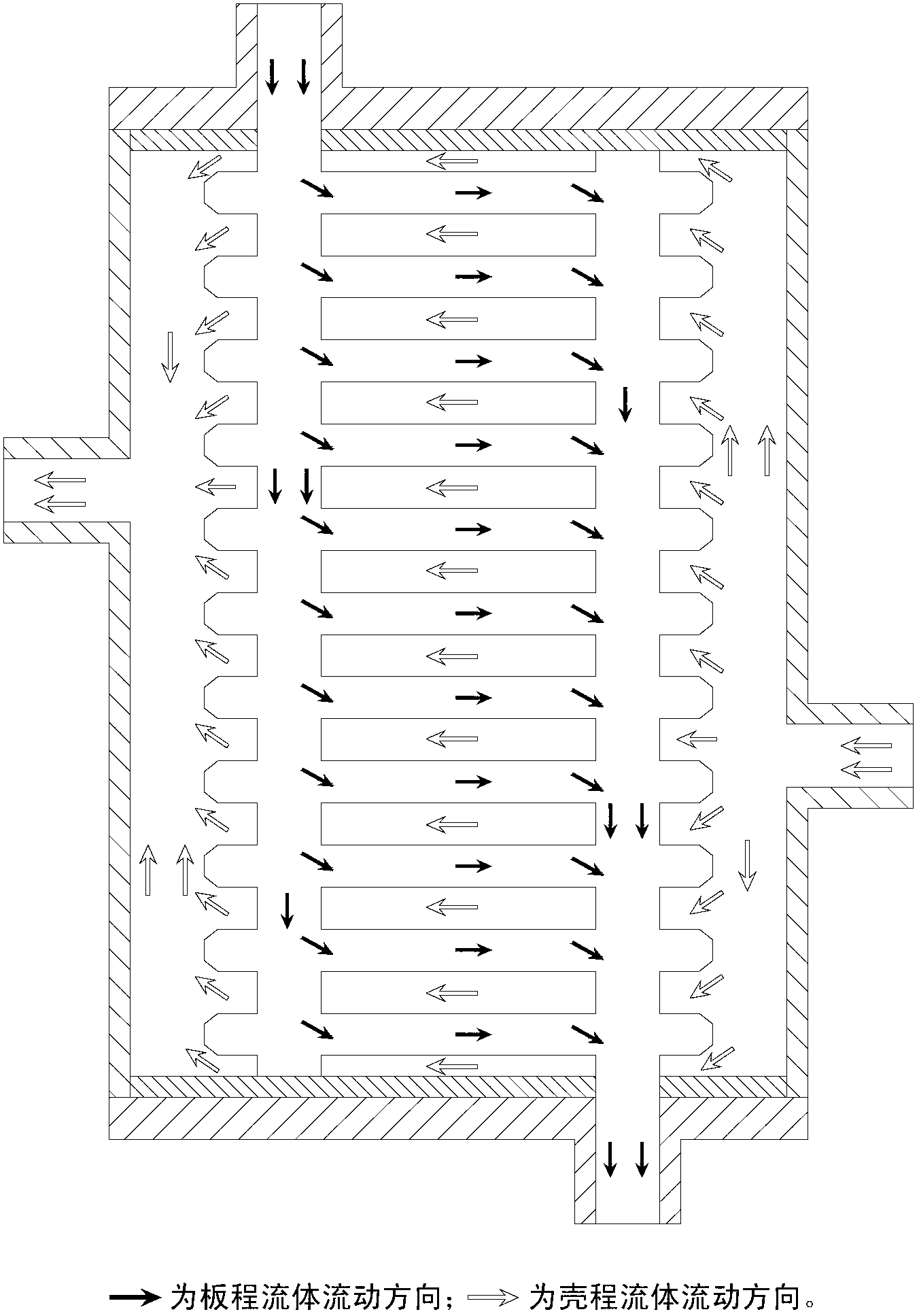
[0025] combine Figure 1~5 , the present invention is made up of board pass inlet 1, board pass outlet 7, shell pass import 9, shell pass outlet 3, shell pass inlet chamber 14, shell pass outlet chamber 12, corrugated plate bundle 5, support plates 6, 10, The deflector blocks 11 and 13, the cover plates 2 and 8 on both sides, and the housing 4 are composed of components. The corrugated plate bundle 5 is welded to the support plates 6, 10 through corner holes, and placed in the housing 4 through the support plates 6, 10. The two ends of the plate bundle 5 are compressed and fixed by the cover plates 2 and 8 . The cover plates 2, 8 are welded with the shell 4 to form a complete shell, which encloses the corrugated plate bundle 5 and the supporting plates 6, 10 inside. The annular area between the shell and the plate bundle is divided into a shell-side inlet chamb...


PUM


Abstract

The invention aims to provide a high-pressure resistant lamella heat exchanger adopting round corrugated plates, which includes a shell, cover plates, a corrugated plate lathed bundle, flow guiding blocks and support plates, wherein the corrugated plate lathed bundle includes corrugated plates and is fixed in the shell through the support plates; the two ends of the shell are sealed by the cover plates; a shell side outlet and a shell side inlet are arranged in the shell; a plate side inlet and a plate side outlet are arranged in the cover plates; an annular zone between the shell and the corrugated plate lathed bundle is divided into a shell side inlet chamber and a shell side outlet chamber through the flow guiding blocks; the shell side inlet is communicated with the shell side inlet chamber; the shell side outlet is communicated with the shell side outlet chamber; angular holes are formed in the corrugated plate lathed bundle; and the plate side inlet is communicated with the plate side outlet through the angular holes in the corrugated plate lathed bundle. The high-pressure resistant lamella heat exchanger provided by the invention has the advantages of high pressure bearing capability, high heat exchange efficiency, compact structure, big heat transfer area in a unit volume, wide material selection range, wide application range, as well as simplicity in processing and installation.

Description

technical field [0001] The invention relates to a heat exchanger in the technical field of enhanced heat exchange. Background technique [0002] Plate heat exchangers are widely used in energy, power, heating, refrigeration and other fields due to their high heat transfer efficiency and compact structure. With the maturity of plate heat exchanger technology, it has replaced the traditional shell and tube heat exchanger in some fields. However, the existing rectangular plate heat exchanger generally has the problem of low pressure bearing capacity. In petrochemical and other common high-pressure fields, the application of plate heat exchangers has been greatly restricted. Developing a plate heat exchanger that can withstand high pressure and has a compact structure has broad application prospects in the field of energy and power. Although there are some fully welded plate and shell heat exchangers at present, their working pressure generally does not exceed 4.5MPa, and the...

Claims


Application Information

Patent Timeline
Patent Type & Authority Applications(China)
IPC IPC(8): F28D9/00F28F3/08
Inventor 丁铭王佳卓阎昌琪石帅陈哲雨
Owner HARBIN ENG UNIV
Learn More