Radio frequency power detection circuit

A technology for detecting circuits and radio frequency power, which is applied in the direction of measuring electrical variables, electrical power measurement by applying digital technology, measuring devices, etc., which can solve the problems of low linearity of mixers and easy saturation of mixers.

Inactive Publication Date: 2012-10-03
FUDAN UNIV
View PDF8 Cites 20 Cited by
  • Summary
  • Abstract
  • Description
  • Claims
  • Application Information

AI Technical Summary

Problems solved by technology

[0004] The linearity of the mixer in the receiver is usually low, and when the input signal strength is high, the mixer is easy to saturate

Method used


Image

  • Radio frequency power detection circuit
  • Radio frequency power detection circuit
  • Radio frequency power detection circuit

Examples


Embodiment Construction

[0024] The present invention will be described in further detail below in conjunction with the accompanying drawings and specific embodiments.

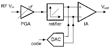
[0025] figure 1 The structure diagram of the radio frequency power detection circuit provided for the present invention includes a programmable gain amplifier (PGA), a half-wave rectifier (rectifier), an instrumentation amplifier (IA) and a 6-digit digital-to-analog converter (DAC). The output voltage of the instrumentation amplifier and the gain control word of the programmable gain amplifier jointly complete the indication of the current input power intensity.

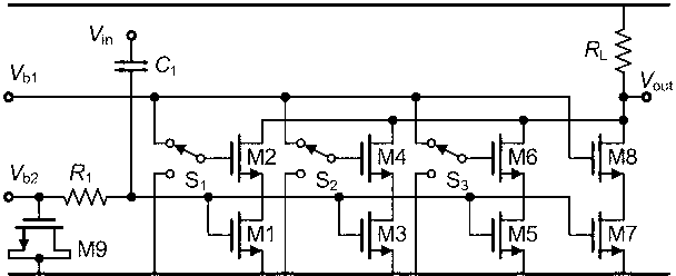
[0026] figure 2 Programmable amplifier used in the present invention. The amplifier has 4 cascode branches in total, among which the cascade connection of NMOS transistor M1 and NMOS transistor M2, the cascade connection of NMOS transistor M3 and NMOS transistor M4, and the cascade connection of NMOS transistor M5 and NMOS transistor M6 constitute optional cascode branche...


PUM


Abstract

The invention belongs to the technical field of automatic gain control of a radio frequency receiver and specifically relates to a radio frequency power detection circuit. The radio frequency power detection circuit comprises a programmable gain amplifier, a half wave rectifier, an instrumentation amplifier and a six-bit digital to analog converter. The programmable gain amplifier is controlled by two-bit digital logic, a gain step is 3-decibel, and a gain range is 9-decibel; the half wave rectifier is connected with the rear of the programmable gain amplifier, a detection for an input power in a fixed range is completed by the half wave rectifier, and the power range is a working range of the rectifier; signals with different power can be amplified to the working range of a rectifier by an optional gain of an amplifier; and finally the instrumentation amplifier is used for amplifying a direct-current output of the half wave rectifier. The rectifier and the instrumentation amplifier can generate output offset voltages caused by a device mismatch, due to offset direct-current voltages, output voltages of a power detection circuit exceed a measuring range of an analog to digital converter, and a six-bit current type full binary digital to analog converter is used for performing an offset pre-distortion for the circuit.

Description

technical field [0001] The invention belongs to the technical field of automatic gain control in radio frequency receivers, in particular to a power detection circuit, in particular to a power detection circuit capable of detecting radio frequency terminal signals. Background technique [0002] The existing digital TV terrestrial transmission standard stipulates that the RF TV tuner can work normally within a large dynamic range of the input signal to ensure the signal-to-noise ratio (SNR) required by digital demodulation, such as the U-band signal of the CMMB standard: -95dBm ~-10dBm, DVB-T signal: -90dBm~-20dBm. At the same time, the tuner should also meet the requirement that the signal strength finally input to the baseband analog-to-digital converter reaches its optimal input power, so as to ensure that the analog-to-digital converter produces less quantization noise. Therefore, the tuner is required to be able to reasonably set the gain according to the signal strengt...

Claims


Application Information

Patent Timeline
Patent Type & Authority Applications(China)
IPC IPC(8): G01R21/133G01R35/00
Inventor 唐长文唐聪
Owner FUDAN UNIV
Why Eureka
Try Eureka