Control method of 3D (Three-Dimensional) glasses system

A technology of 3D glasses and a control method, applied in stereoscopic systems, optics, instruments, etc., can solve problems such as strong sense of oppression, complex structure, and non-consideration, and achieve good effects and direct adjustment methods

Inactive Publication Date: 2012-10-03
夏德虎
View PDF0 Cites 9 Cited by
  • Summary
  • Abstract
  • Description
  • Claims
  • Application Information

AI Technical Summary

Problems solved by technology

[0004] However, the shutter-type 3D glasses in this traditional 3D glasses system also have the following disadvantages: the traditional shutter-type 3D glasses can only quickly switch the video perceived by the left and right eyes, that is, realize the function of opening and closing, thereby generating Three-dimensional effect, but it does not take into account the visual impact caused by the distance between the user and the 3D TV, that is, if the user is relatively close to the 3D TV, the light will be too strong and the user will often feel glare. Longer, the visual fatigue is more likely to be harmful to health. Therefore, if the brightness of the shutter 3D glasses (that is, the light transmittance of the liquid crystal lens) can be manually adjusted, it will greatly facilitate the user's needs in use.
[0008] In addition, the current shutter-type 3D glasses, because its start-up control module is generally divided into two parts (such as a battery and a circuit board), which are respectively arranged in two temples. The shutter-type 3D glasses with this structure have both temples. It is designed as a two-layer sandwich structure, and its internal space is used for wiring. Therefore, this kind of glasses are generally large in size and heavy in weight. When worn for a long time, the pressure is strong, the structure is also relatively complicated, and the power loss in the transmission process Also larger and more expensive

Method used


Image

  • Control method of 3D (Three-Dimensional) glasses system
  • Control method of 3D (Three-Dimensional) glasses system
  • Control method of 3D (Three-Dimensional) glasses system

Examples


Embodiment 1

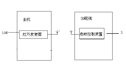
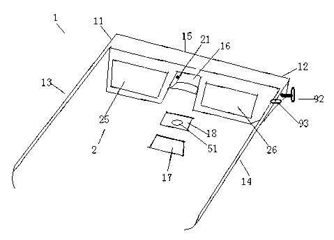
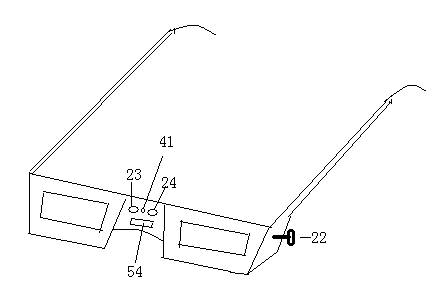
[0042] Such as Figure 1-4 As shown, Embodiment 1 of the present invention provides a 3D glasses system. The 3D glasses system includes a host and 3D glasses, the host includes an infrared emitter 100 for transmitting synchronous video signals through infrared rays, the 3D glasses include a spectacle frame 1, a liquid crystal spectacle lens 2 and a start control device 3, the The spectacle frame 1 comprises a left spectacle frame 11, a right spectacle frame 12, a left spectacle leg 13, a right spectacle leg 14, and a middle nose pad 15 connecting the left spectacle frame 11 and the right spectacle frame 12, and the middle nose pad 15 is The hollow structure includes an accommodating cavity 16 formed by indenting the inner side surface of the middle nose pad 15 and a cover 17 covering the accommodating cavity 16 .

[0043] The start control device 3 includes a signal receiving module 4, a power management module 5 and a central control module 6, and the liquid crystal spectacl...

Embodiment 2

[0058] Embodiment 2 of the present invention provides a control method using the 3D glasses system in Embodiment 1.

[0059] After adopting the 3D glasses system in Embodiment 1, the following control method can be used to operate the 3D glasses system.

[0060] Step S100, using the infrared emitter in the host to transmit the synchronous video signal through infrared rays; it may specifically include: the host includes a photocoupler, a microprocessor and an infrared emitter, and the photocoupler outputs the input stereo playback device The synchronous signal is converted into a corresponding voltage signal, which is input to the detection terminal of the microprocessor; the microprocessor is encoded and modulated into a synchronous video signal according to a certain format according to the voltage signal input by the photocoupler, and then output to the infrared transmitter ; The infrared transmitter emits the synchronous video signal through infrared rays;

[0061] Step S...

Embodiment 3

[0070] Such as Figure 8 As shown, Embodiment 3 of the present invention provides another 3D glasses system. The difference from Embodiment 1 is that the structure of the video control modules is different, and they can be used interchangeably. The video control module 7 in the third embodiment includes a video processing module 71, a video adjustment module 72 and a video driving module 73, wherein the video processing module 71 is used to process the first video synchronization signal including amplification and filtering obtain the second video synchronous signal, the video adjustment module 72 is used to adjust the magnitude of the second video synchronous signal to obtain a third video synchronous signal, and the video driver module 73 is used to obtain the third video synchronous signal according to the third video The synchronous signal generates a video synchronous driving signal, and the liquid crystal spectacle lens 2 is controlled to open and close alternately by t...


PUM


Abstract

The invention discloses a control method of a 3D (Three-Dimensional) glasses system. The control method of the 3D glasses system comprises a pair of 3D glasses. The pair of 3D glasses comprises a glasses frame, liquid crystal glasses lenses and a start control device. The start control device comprises a signal receiving module, a power supply management module and a central control module. The central control module comprises a video control module. Each liquid crystal glasses lens comprises a connecting terminal connected to an LCD (Liquid Crystal Display) drive module in the video control module. The connecting terminal passes through a left glasses frame and a right glasses frame close to a middle node pad and extends into a receiving cavity. The left glasses frame or the right glasses frame comprises a first knob connected to an LCD time sequence adjusting module in the video control module. The first knob is used for the user to manually adjust the amplitude of a time sequence waveform received by the LCD time sequence adjusting module. The light transmittance of the liquid crystal glasses lenses can be manually adjusted directly by this way.

Description

technical field [0001] The invention relates to a control method of a 3D glasses system, in particular to a control method of a 3D glasses system including shutter-type 3D glasses with a simple structure and capable of manually adjusting light transmittance. [0002] Background technique [0003] The shutter-type 3D glasses in the common 3D glasses system generally include a picture frame and mirror legs, wherein the picture frame includes two liquid crystal lenses and a signal receiver, and the signal receiver is used to receive wireless signals (such as infrared video signals, wireless audio signal), and decode the wireless signal, from which the video and audio synchronization signals are decoded, the circuit board and the battery are packaged in the temple, and the circuit board includes a central processing and control unit (such as a central processing chip CPU or a microcontroller MCU, etc.), video signal driving circuit and audio signal driving circuit and other cir...

Claims


Application Information

Patent Timeline
Patent Type & Authority Applications(China)
IPC IPC(8): G02B27/22H04N13/04
Inventor 夏德虎
Owner 夏德虎
Why Eureka
Try Eureka